Is Holtz Garden Center Still Open In Cedarburg Wi
Abstract
We present evidence that in ~ 1650 BCE (~ 3600 years ago), a cosmic airburst destroyed Tall el-Hammam, a Middle-Bronze-Age city in the southern Jordan Valley northeast of the Dead Sea. The proposed airburst was larger than the 1908 explosion over Tunguska, Russia, where a ~ 50-m-wide bolide detonated with ~ 1000× more energy than the Hiroshima atomic bomb. A city-wide ~ 1.5-m-thick carbon-and-ash-rich destruction layer contains peak concentrations of shocked quartz (~ 5–10 GPa); melted pottery and mudbricks; diamond-like carbon; soot; Fe- and Si-rich spherules; CaCO3 spherules from melted plaster; and melted platinum, iridium, nickel, gold, silver, zircon, chromite, and quartz. Heating experiments indicate temperatures exceeded 2000 °C. Amid city-side devastation, the airburst demolished 12+ m of the 4-to-5-story palace complex and the massive 4-m-thick mudbrick rampart, while causing extreme disarticulation and skeletal fragmentation in nearby humans. An airburst-related influx of salt (~ 4 wt.%) produced hypersalinity, inhibited agriculture, and caused a ~ 300–600-year-long abandonment of ~ 120 regional settlements within a > 25-km radius. Tall el-Hammam may be the second oldest city/town destroyed by a cosmic airburst/impact, after Abu Hureyra, Syria, and possibly the earliest site with an oral tradition that was written down (Genesis). Tunguska-scale airbursts can devastate entire cities/regions and thus, pose a severe modern-day hazard.
Introduction
Since 2005, archeological excavations have been conducted at Tall el-Hammam ("TeH"), an ancient walled city in the southern Jordan Valley located northeast of the Dead Sea (Fig. 1). The ruins are situated in a part of the Great Rift Valley known as the Middle Ghor, defined as the southern end of the valley between Lake Tiberias, Israel at ~ 200 m below sea level (mbsl), and the Dead Sea at ~ 415 mbsl. This area represents the southernmost 25 km of the Jordan River drainage, where the valley floor north of the Dead Sea is a relatively flat and disk-like plain, called "the Kikkar of the Jordan" (hakikkar hayarden) in Hebrew1,2.
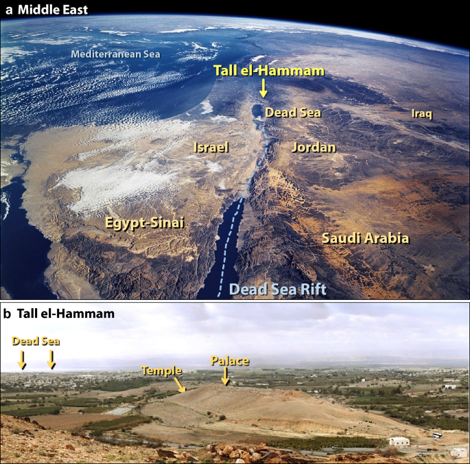
Location of Tall el-Hammam. (a) Photo of the southern Levant, looking north, showing the Dead Sea, the site location (TeH), and nearby countries. The Dead Sea Rift, the fault line marking a major tectonic plate boundary, runs through the area. Source of base image: NASA, Space Shuttle. "The Sinai Peninsula and the Dead Sea Rift". Photo: sts109-708-024, taken 12/16/2009. From the NASA Langley Research Center Atmospheric Science Data Center (nasa.gov/topics/earth/features/astronauts_eyes/sts109-708-024.html). Modified by the authors using Adobe Photoshop CC2014 (adobe.com/products/photoshop.html). (b) West-southwest-facing view of the upper tall showing locations of the palace and temple behind the curve of the upper tall. The Dead Sea is in the background to the left.
Full size image
TeH is a raised, two-tiered occupational mound, the largest in the Jordan Valley. A mound of ancient ruins is referred to as "tel" in Hebrew and "tell" or "tall" in Arabic. The site contains the stratified remains of a fortified urban center, now known as the largest continuously occupied Bronze Age city in the southern Levant1. More than just a mere city, TeH comprised the urban core of a city-state that flourished nonstop for ~ 3000 years during the Chalcolithic Period and Bronze Age beginning ~ 4700 BCE until it was destroyed at ~ 1650 BCE (3600 cal BP). This investigation focuses on the Middle Bronze Age II (MB II) from ~ 1800–1550 BCE. For archaeological periods and date ranges for the Jordan Valley, see Supporting Information, Text S1. All dates and ages reported here are as BCE, "Before Common Era," and occasionally in calendar years before the year 1950 (cal BP).
The project is under the aegis of the School of Archaeology, Veritas International University, Santa Ana, CA, and the College of Archaeology, Trinity Southwest University, Albuquerque, NM, under the auspices of the Department of Antiquities of the Hashemite Kingdom of Jordan. The extensive, ongoing excavations at TeH have continued for fifteen consecutive seasons since 2006, involving principal investigators assisted by graduate and doctoral students and large numbers of volunteers from across North and South America, Europe, Africa, Asia, Australia, New Zealand, and the Near East2,3,4,5,6,7. In addition to the usual debris patterns typical of ancient cities destroyed by warfare and earthquakes, the excavations of the final phase of the MB II stratum revealed highly unusual materials: pottery sherds with outer surfaces melted into glass, some bubbled as if 'boiled'; melted and 'bubbled' mudbrick fragments; partially-melted roofing clay (with wattle impressions); and melted building plaster. These suggest that the city's destruction was associated with some unknown high-temperature event.
The ~ 1.5-m-thick MB II destruction matrix also exhibited rare properties not found in the strata above or below it. Sherds from thousands of different pottery vessels were randomly intermixed and distributed throughout the depth of the matrix along with mudbrick fragments, objects of daily life, carbonized pieces of wooden beams, charred grain, bones, and limestone cobbles burned to a chalk-like consistency. At the very least, the nature of the MB II destruction matrix is highly unusual and atypical of archaeological strata throughout the ancient Near East3.
Geological context
The Middle Ghor is marked by a major tectonic boundary separating the Arabian and African Plates (Sinai-Palestinian subplate) running through the Gulf of Aqaba/Dead Sea/Jordan Valley region. The resulting Dead Sea Rift is a highly active pull-apart strike-slip fault with largely horizontal left lateral motion. For the past 15 million years, motion along the plate boundary has been in a north–south direction (Fig. 1). Geological evidence indicates an average horizontal displacement rate of at least one cm per year along this fault system, producing a recurring cycle of strong earthquakes (M ≥ 7) approximately every 1400 years8.
Exposed rock formations on the eastern slopes of the Jordan Valley near the Dead Sea shoreline are of late-Cambrian age (~ 500 Ma) and consist of ~ 300 m of brick-red, fluvial, quartz-rich sandstone9. These sediments are unconformably overlain by a basaltic sequence ~ 5 Myr in age. The eastern edge of the Jordan Valley contains an even younger sequence consisting of reddish conglomerates and laminated marls, interlayered with gravels and sandstones. These, in turn, are capped by a latest Quaternary sequence of alluvial and colluvial sediments exposed on the valley floor on the eastern side of the Middle Ghor near TeH.
Lake Lisan, the precursor to the modern Dead Sea, began to fill about 80,000 years ago, reaching a maximum level of 170–185 mbsl by ~ 18,000 cal BP10. What remains of Lake Lisan is now known as the Dead Sea, landlocked and considered "dead" because of its hypersalinity at ~ 34 wt.% salt. Consequently, the sea does not support higher organisms, such as aquatic plants and fish. During Middle Bronze Age I (MB I; ~ 2000–1800 BCE) rainfall was more plentiful, and the level of the Dead Sea rose to about 370 mbsl, at least ~ 50 m higher than its current elevation of 430 mbsl. At that time, the eastern shore of the Dead Sea was likely several km closer to TeH11. Toward the end of MB II, the lake level dropped as low as 430 mbsl, as indicated by a windblown sand layer in Dead Sea sediment cores11,12.
Human occupation of the Jordan Valley
Located in a generally arid region, the Jordan Valley is one of the best-watered areas in all of the southern Levant (Jordan, Israel, and Palestine). In addition to numerous springs created by a disgorging Transjordanian aquifer, the area had hydrological conditions for human habitation somewhat analogous to the Nile Delta region, which is also bordered by arid terrain. The Middle Ghor near TeH supported a large human population. During MBA peak occupation, at least an estimated 50,000 people occupied three major cities, plus satellite towns, villages, and hamlets spread across ~ 400 km2 of the eastern Kikkar13.
The earliest significant human settlement in the Middle Ghor area was Tuleilat Ghassul near the northeast corner of the Dead Sea ~ 5 km from TeH, initially settled during the Late Neolithic Period (> 6600 cal BP). By the Chalcolithic Period (~ 6600–5500 cal BP), the inhabitants had developed considerable skill as pottery makers13, and by the Early Bronze Age, the Middle Ghor was extensively settled at > 100 separate locations.
The three largest settlements in this area were TeH, Tall Nimrin, and Jericho (aka, Tell Es-Sultan), urban anchors of three city-state clusters, each surrounded by numerous smaller satellite towns and villages. At 36 hectares of fortifications (0.36 km2) and an additional 30 hectares of "suburban sprawl," TeH at its zenith was > 4× larger than Tall Nimrin14 and > 5× larger than Jericho15, and thus, was likely to have been the area's politically dominant MBA urban center for many centuries16. TeH was initially occupied during the early Chalcolithic Period (~ 6600 cal BP) and was a well-established fortified urban center by the Early Bronze Age (~ 5300 cal BP). The city reached its peak of hegemony during the MBA and dominated the eastern half of the Middle Ghor and most likely, the western half as well. Then suddenly, the occupation of TeH ceased at ~ 1650 BCE (~ 3600 cal BP) at the end of MB II, followed by an enigmatic ~ 600-year occupational hiatus. The site was not substantially occupied again until much later in the Iron Age.
The catastrophic destruction of Tall el-Hammam
The upper tall at TeH had massive ~ 4-m-thick city wall foundations supporting freestanding mudbrick ramparts, multi-story mudbrick buildings including a palace complex (Fig. 2a), and a monumental gateway. Today, almost no mudbricks remain on MB II stone foundations except for a dozen or so mudbrick courses surviving on the northeast side of the 33-m-high upper tall, where no MB II mudbrick superstructure stands more than 12–15 courses high. All walls are seemingly sheared off nearly level with the tops of the upper-city wall foundations, many of which have several surviving mudbrick courses. This includes the massive palace complex that once had walls ranging from 1.0 to 2.2 m in thickness and likely rising to ~ 11–15 m in height.
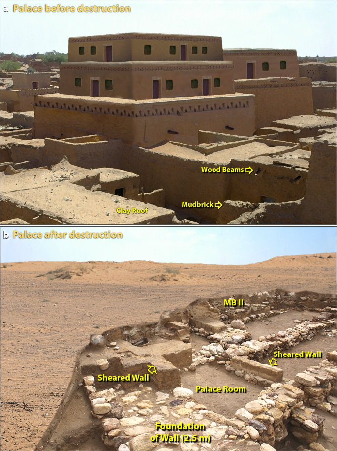
Catastrophic leveling of the palace at TeH. (a) Artist's evidence-based reconstruction of the 4-to-5-story palace that was ~ 52 m long and 27 m wide before its destruction. (b) Artist's evidence-based reconstruction of palace site on upper tall, along with modern excavation. "MB II" marks the top of 1650-BCE Middle Bronze rubble. Note that the field around the excavation is essentially flat, unlike the view in panel 'a'. Originally, parts of the 4-story palace were ~ 12 + m tall, but afterward, only a few courses of mudbricks remain on stone foundations, labeled as "wall remnants". Part of the foundation of the massive wall around the palace is at the bottom. Debris from between sheared walls has been removed by excavation. A comparison of panel 'a' to panel 'b' shows that millions of mudbricks from the upper parts of the palace and other buildings are missing.
Full size image
In addition to the outer rampart surrounding the lower city, a formidable upper-city rampart-and-wall defensive system protected the acropolis palace on three sides, and a 2.2-m-thick wall separated the raised palace platform from the rest of the upper city. The rampart itself, constructed from millions of mudbricks, was as much as ~ 30 m thick at the base and ~ 7–8 m thick at the top, wide enough for military patrols. A 4-m-thick mudbrick defensive wall on stone foundations with towers lined the outer edge at the top of the rampart, rising more than 33 m above the lower city.
The ~ 4–5-story-tall palace complex (~ 52 m × ~ 27 m), with massive superstructures made of sun-dried mudbricks (Fig. 2a), extended ~ 11–15 m above the top of the enclosing rampart. The palace excavations reveal that most of the first-floor walls and all of the upper stories of the MB II palace are missing, with no evidence of collapsed walls across the entire upper tall. There are almost no whole mudbricks visible anywhere, and instead, small fragments of bricks are randomly strewn around as infill within the churned-up, 1.5-m-thick destruction matrix. It appears that most bricks were pulverized and blown off the site to the northeast (Figs. 2b, 3; Supporting Information, Fig. S1).
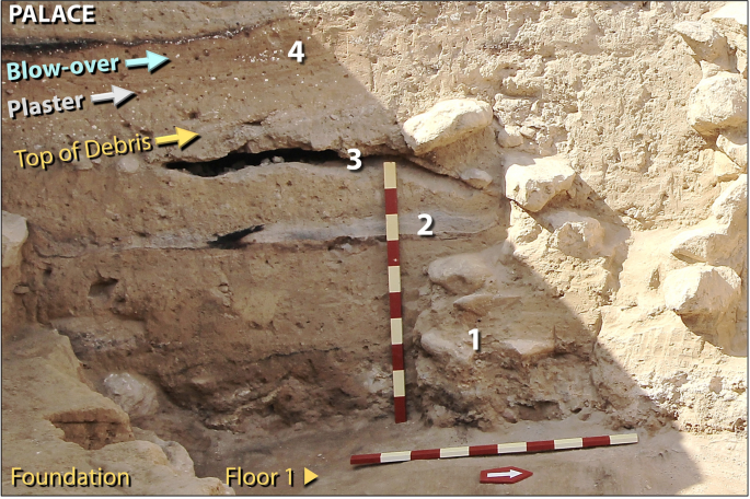
Destruction of the multi-storied palace. Photo showing jumbled rubble of four-story Palace atop Floor 1. Remains of debris from upper stories are labeled as follows. #1 represents broken mudbricks and debris from shattered upper walls. #2 and #3 are voids and layers formed when trapped textiles (rugs and tapestries) burned, leaving only fibrous ash and carbon. 'Blow-over' (in blue) is composed of windblown, laminated deposits that sealed the ruined structure for ~ 3600 years, beginning at the time of destruction. #4 marks fragments of white limestone plaster (CaCO3) mixed with carbonate spherules from the palace walls and ceiling. Scale stick has 10-cm markings.
Full size image
On the lower tall, these general characteristics also apply. However, the MB II structures, particularly in the south, southwest, and west sectors of the lower city, seem to have suffered greater damage. For example, virtually no mudbricks survive on the stone foundations of lower city domestic structures, even on the massive stone foundations of the 4–5-m-thick MB II city wall. Additionally, some of the large finishing stones of the city wall and associated pillar-bases of a monumental gateway show signs of heat fracturing. There are several courses of mudbricks surviving on the external towers flanking the MB II monumental gateway, but only to the height of the city wall stone foundations. The remains of the MB II stratum on the lower/outer city are largely exposed at the surface, with little to no evidence of erosional mudbrick detritus across the entire lower tall, similar to what is found on the upper tall. A heavy concentration of salt-laden ash makes up most of the shallow soil that covers the lower tall. More than 98% of the area of the lower tall was never built upon again during the 3600 years after the MB II terminal destruction3.
Although few-to-no MB II mudbrick courses remain on the lower tall, up to a dozen mudbrick courses remain on their stone foundations on the northeastern sector behind the high-rising upper city defensive ramparts. This strongly suggests that whatever destroyed TeH exhibited greater intensity across the southwest-facing sector. This also applies to the upper tall where excavated structures extend only to the height of the rampart and remaining upper-city wall foundations. Inside the depression created by the massive, surrounding defenses, all the MB II walls from 0.5 to more than 2 m in thickness are sheared off at half the height (~ 1.5 m) of the first story. Excavations across the entire upper and lower talls are consistent in showing the most damage on the southwest exposure of the lower city.
In summary, the few remaining mudbricks from disintegrated wall sections are mostly pulverized, rarely found intact, and sometimes reddened by fire. Across the entire upper and lower tall, the MB II terminal destruction matrix shows no signs of natural erosion by either wind or water, meaning that the missing mudbricks have not eroded over time. This means that millions of mudbricks are missing (Fig. 2b). Here, we investigate what happened to them.
Study objectives
The major objective of this contribution is determining the processes involved in the high-temperature, catastrophic destruction of Tall el-Hammam, a prosperous, powerful MB-II urban center. Early archaeological excavations at TeH revealed the presence of unusual materials, including melted mudbrick fragments, melted roofing clay, melted pottery, ash, charcoal, charred seeds, and burned textiles, all intermixed with pulverized mudbrick. After eleven seasons of excavations, the site excavators independently concluded that evidence pointed to a possible cosmic impact. They contacted our outside group of experts from multiple impact-related and other disciplines to investigate potential formation mechanisms for the unusual suite of high-temperature evidence, which required explanation.
We conducted a wide range of analyses, using many analytical approaches that included optical microscopy, scanning electron microscopy (SEM) with energy-dispersive spectroscopy (EDS), microprobe, focused ion-beam milling, cathodoluminescence, and neutron activation. Our group analyzed 38 elements, minerals, and other materials (Table 1), and of these, 74% (n = 28 of 38) melt at ≥ 1300 °C; 45% (n = 17 of 38) at ≥ 1600 °C; and 18% (n = 7 of 38) at ≥ 2000 °C. All represent equilibrium temperatures, which are usually a few hundred degrees higher than non-equilibrium temperatures commonly associated with oxygen-deficient (reducing) conditions present during impact events17.
Full size table
Potential written record of destruction
There is an ongoing debate as to whether Tall el-Hammam could be the biblical city of Sodom (Silvia2 and references therein), but this issue is beyond the scope of this investigation. Questions about the potential existence, age, and location of Sodom are not directly related to the fundamental question addressed in this investigation as to what processes produced high-temperature materials at Tall el-Hammam during the MBA. Nevertheless, we consider whether oral traditions about the destruction of this urban city by a cosmic object might be the source of the written version of Sodom in Genesis. We also consider whether the details recounted in Genesis are a reasonable match for the known details of a cosmic impact event.
Stratigraphy of Tall el-Hammam
Our investigations focused on suites of samples from four representative sampling sites, spanning a lateral distance of ~ 1500 m across the occupational mound of Tall el-Hammam and into the watershed beyond (Fig. 4, Supporting Information, Fig. S2). Three sampling sites (the palace on the upper tall; the temple on the lower tall; and the ring road on the lower tall near the main gate) were chosen based on access to archeologically excavated squares in the key areas of interest. The wadi site was chosen because of its location outside the city walls. The three sites in the city are separated by up to ~ 500 m laterally, covering an area of 5.7 ha (0.057 km2). The wadi site extends the total horizontal distance to 1500 m for all 4 sites. Sample collection from more distant sites outside the tall could not be conducted due to lack of access. Attempts to widen the sampling area are ongoing.
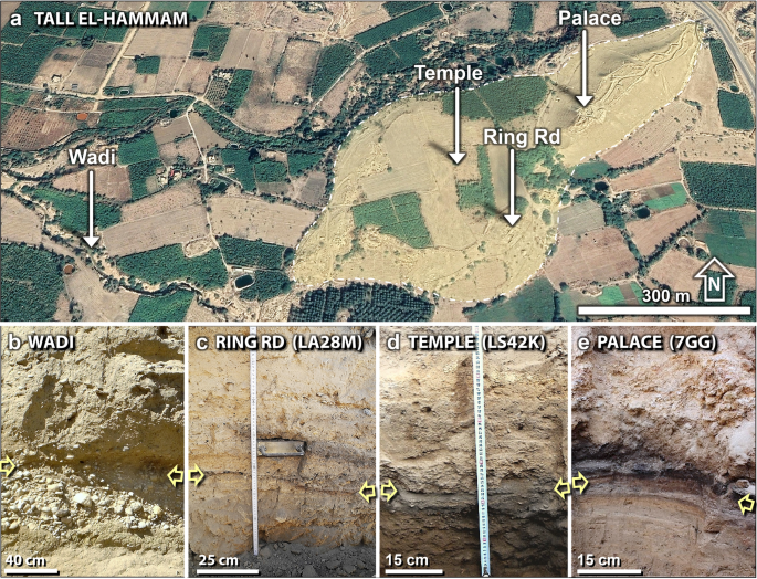
Sedimentary profiles. (a) Map of the city (white dashing line) showing sampling locations, spanning ~ 1100 m. Source of base image: "Tall el-Hammam". 31° 50.483 N, 35° 40.029 E. Google Earth; CNES/Airbus. Imagery date: 11/26/2019; accessed: 4/4/2021. (b) The wadi; (c) the ring road in Field LA; (d) the palace in Field LS; and (e) the palace in Field UA. In the wadi, yellow arrows mark the level of the 3600-year-old stratum. Inside the city, the arrows mark the location of the charcoal-and-ash-rich dark layer.
Full size image
All TeH sampling profiles investigated contain an MB II burn layer that is highly complex and variable across the tall but is generally composed of three parts. The first part is the deepest one and is mainly pulverized mudbrick, mixed with larger melted and unmelted mudbrick fragments, melted and unmelted roofing clay, ash, charcoal, charred seeds, unburnt wood, burned textiles, bones, plaster fragments, broken pottery, and melted pottery. We call this the 'debris matrix'. It varies in thickness up to ~ 1.5 m and is only occasionally missing across the entire tall.
The second part, immediately above the debris matrix, is composed of thin, windblown, fine-grained laminations, including fragments of broken plaster, limestone spherules, and charcoal, radiocarbon-dated to 1650 BCE. It is not present in all locations and instead, is typically found on the NE sides of SW-facing wall remnants at the top of the debris matrix. This extraordinary stratum is termed the 'blow-over layer'. Nothing similar has been identified in any older or younger deposits, beginning in the Early Bronze Age and extending through the Iron Age.
The third part is a charcoal-and-ash-rich stratum that we call the 'dark layer,' which is found everywhere across the tall and is typically only a few centimeters thick or less. However, on the outer, southwest-facing side of the large city gate, it is ~ 1 m thick. Sometimes, the dark layer is present on top of the blow-over layer, but other times, it is the only layer found, usually resting on top of an existing interior building floor. Its depth of burial varies considerably from being near the surface on parts of the lower tall to being buried 1–4 m across most of the upper tall. The debris matrix, the blow-over, and the dark layer collectively comprise the interval of interest called the 'destruction layer'.
The four sites investigated, with a difference in elevation of 52 m, are listed below from SW to NE. Almost all proxies investigated here came from these four sampling sites:
- (i)
The wadi: the surface is at an elevation of ~ 197 mbsl on a short seasonal stream that drains the southern boundary of the tall (Fig. 4b, Supporting Information, Fig. S2). We sampled a 170-cm-thick sequence beginning ~ 100 cm below the surface with the destruction layer at ~ 160 cm below the surface. Five discontinuous samples had an average thickness of ~ 13.2 cm (range 10–20 cm). Four intermediate layers were not sampled. The average sample size for the wadi and the three following sites was 1200 g (range 870–2000 g).
- (ii)
Ring road: the surface is at ~ 170 mbsl on the road interior to the wall that ringed the lower city (Fig. 4c, Supporting Information, Fig. S2). The top of the 30-cm sequence is at a depth of 22 cm with the destruction layer at 42 cm. Six contiguous samples each had thicknesses of 5 cm.
- (iii)
Temple: the surface is at ~ 170 mbsl on the lower tall (Fig. 4d, Supporting Information, Fig. S2). We sampled a 43-cm sequence, with the destruction layer at 54 cm. Five contiguous samples had an average sample thickness of 8.6 cm (range 6–16 cm).
- (iv)
Palace: the surface is at ~ 145 mbsl on the upper tall (Fig. 4e, Supporting Information, Fig. S2). We sampled a 28-cm sequence with the top of the destruction layer at ~ 360 cm. Five contiguous samples each had an average thickness of 5.6 cm (range 3–13 cm).
Radiocarbon age of destruction layer
The age of the destruction layer at TeH was modeled using the OxCal radiocarbon calibration program18,19, version 4.4 (IntCal20 calibration curve) with the 'Combine' computer routine20 (Supporting Information, Tables S1, S2). Radiocarbon dates were obtained for 26 samples from the destruction layer, and of those, three dates were rejected by OxCal as outliers that are a few decades too young, and three dates were rejected as being a few decades too old. The following datable materials were extracted from the destruction layer in Field UA in and around the palace: carbonized wood, including twigs (n = 11), carbonized grains and seeds (n = 3), charred organic material (n = 4), organic sediment (n = 1), and collagen from burned bone (n = 1).
The Bayesian-modeled age for the destruction layer is 1661 ± 21 BCE (3611 cal BP) (Fig. 5; Supporting Information, Tables S1, S2) for a range of 1686–1632 BCE with a 68% confidence interval (CI, approximately equivalent to 1σ). Because of radiocarbon-dating uncertainties, the age of the destruction event has been rounded to the nearest half-century: 1650 BCE ± 50 (3600 cal BP). This age is consistent with seriation, a standard dating method used in archaeology based on the ages of stylistic changes in pottery and artifacts. This method provides an estimated age of ~ 1750–1650 BCE2.
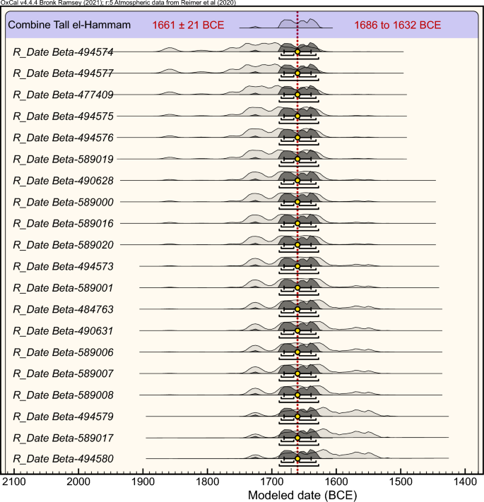
Bayesian analysis. Using OxCal v.4.4.418,19,20, the 'Combine' computer routine determined that 20 of 26 14C dates are statistically synchronous and likely represent a single event at 1661 ± 21 BCE (1686–1632 BCE), rounded to 1650 BCE. Light gray curves represent unmodeled calibrated ages; dark gray represents modeled calibrated ages. The white dot beneath the curves equals the mean age, also represented by the red dotted vertical line. Progressively longer brackets beneath curves represent 68% and 94% confidence intervals. The program performed two statistical probability tests to test the robustness of the model. Both the Acomb and Chi Sq statistical tests show a high probability, indicating that the modeled age of 1661 ± 21 BCE is likely to be accurate.
Full size image
Discussion of the radiocarbon age for Tall el-Hammam
The accurate radiocarbon dating of the destruction layer is a necessary element of the TeH evidence. For maximum accuracy, Telford et al.21 recommended that the age of any short-term event is best constrained by using multiple dates of samples collected directly within a layer of interest. At TeH, we acquired datable carbon only from the clearly defined destruction layer. The seeds represent a single year and some of the charred wood is from twigs representing only a few years' growth. These short-lived materials are among the most desirable for accurate dating, making it likely that the age range of these samples encompasses the true age of the layer.
Nevertheless, there are special difficulties with radiocarbon dating when seeking annual to decadal accuracy. For example, modern accelerator mass spectrometry (AMS) radiocarbon measurements are typically accurate only within ± 20 to ± 30 years. This means that a specific year cannot be assigned to a stratigraphic layer, notwithstanding the widespread but erroneous practice of relying on single-year mean dates and ignoring the uncertainties22. Instead, most radiocarbon dates have ranges of uncertainties that typically span decades. In addition, a measured date of wood may be inaccurate because of the 'old wood effect,' also known as the inbuilt age21,22,23. For example, the burning of a 100-year-old palace wood beam may provide an age of the TeH destruction layer that erroneously appears 100 years too old. Also, carbon-rich materials at archaeological sites commonly are transported vertically due to bioturbation by humans, animals, and plants and by wind-and-water redeposition, making precise and accurate dating more difficult at high chronological resolution.
Bayesian analysis has increasingly become the standard approach to produce archeological age-depth models22 since this dating method minimizes potential stratigraphic complications. The OxCal calibration program, for example, uses a Combine routine that statistically tests the hypothesis that multiple radiocarbon dates relate to the same event. When multiple dates from a single stratum have differing radiocarbon ages, the OxCal program determines which dates have the highest probability of fitting the model, and the anomalous dates are either remodeled or rejected as outliers, thus producing a statistically accurate calibrated radiocarbon age.
Results and interpretations
Contents of this study
The evidence for this investigation is multi-disciplinary and complex, and therefore, to assist with understanding the presentation, we have organized the evidence into eight major sections. A discussion follows each sub-section:
-
Evidence for high-temperature burning of the city. (A1) MBA burn layer in Tall el-Hammam. (A2) Peaks in fire-related carbon proxies. (A3) Diamond-like carbon (diamonoids).
-
Melted construction materials. (B1) Melted Pottery. (B2) Remanent magnetism of melted pottery. (B3) Melted mudbricks. (B4) Melted roofing clay. (B5) Directionality of debris.
-
High-pressure shock metamorphism. (C1) Shocked quartz at Tall el-Hammam. (C2) Shocked quartz grains from known airbursts.
-
High-temperature melted minerals. (D1) Melted quartz grains. (D2) Melted Fe- and Si-rich spherules. (D3) Calcium carbonate spherules and plaster. (D4) Melted zircon grains. (D5) Melted chromite grains. (D6) Nuggets of Ir, Pt, Ru, Ni, Ag, Au, Cr, and Cu in meltglass. (D7) Platinum, iridium, and palladium in sediment. (D8) Meltglass vesicles lined with metal-rich minerals. (D9) Melted iron and titanium. (D10) Melted iron sulfide and iron phosphide. (D11) Melted calcium phosphide. (D12) Melted calcium silicate (wollastonite).
-
Human bones in the destruction layer
-
Implications of high salinity for agriculture
-
Coeval destruction and burning of Jericho
-
Potential causes of the city destruction. (H1) Anthropogenic activities. (H2) Pottery-making. (H3) Normal city fires/wildfires. (H4) Midden fires. (H5) Warfare. (H6) Earthquakes. (H7) Volcanism. (H8) Lightning. (H9) Crater-forming cosmic impact. (H10) Cosmic airburst.
-
Analogous destruction events. (I1) Comparison to Trinity atomic detonation. (I2) Comparison to Tunguska cosmic airburst. (I3) Hypothetical Tunguska-class airburst near Tall el-Hammam.
-
Conclusions.
Evidence for high-temperature burning of the city
MBA burn layer in Tall el-Hammam
The first evidence of burning relevant to this study was unearthed when excavators discovered several 6- to 7-cm-wide pieces of MB II pottery with surfaces that appeared to have been melted at high temperatures1,3,4,5,6,7. Subsequently, the excavators uncovered a burn layer with a large number of melted mudbrick fragments and what appeared to be melted roofing clay1,3,4,5,6,7. Such material is highly anomalous because the MBA inhabitants of the region were unable to produce fires with temperatures high enough to melt such material. These discoveries led to the investigations described in this contribution.
Several post-MBA burn layers were found on the upper tall several meters above the MB II burn layer and dated 300 years younger at ~ 1400 BCE during Late Bronze Age II (Fig. 6). In addition, there are two earthquake-related destruction layers buried beneath the MB II destruction layer; one dates to ~ 3300 BCE during the Early Bronze Age and the other to ~ 2100 BCE during the Intermediate Bronze Age. However, the strata marking those other events do not display the magnitude of destruction or contain any of the melted materials found in the MB II burn layer.
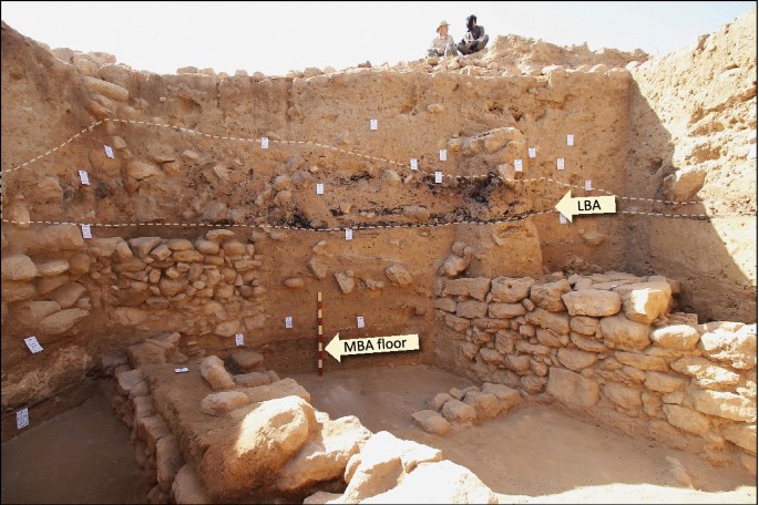
Multiple burned layers at Tall el-Hammam. On the upper tall, there are three terminal burn layers: one during the Middle Bronze Age (MB II), another during Late Bronze Age II (LBA), and one higher during the Iron Age (not visible here). Each burn layer represents the end of an archaeological period at the site. Dashed white line encloses LBA burn layer at arrow, representing the burning of a single building at ~ 1400 BCE stacked atop the sheared MB-II walls. "MBA floor" marks the top of the MB II floor beneath the 1.5-m-thick destruction layer dating to 1650 BCE. Two earthquake-related destruction layers (not shown) are buried deeper than the floor of this excavation, one dated ~ 400 years earlier at ~ 2100 BCE and the other even older at ~ 3300 BCE. All these layers are distinctly separate from the MB II destruction layer above bottom arrow, the only layer that contains high-temperature melted materials.
Full size image
Discussion of city-wide burning and destruction
We considered whether TeH was burned and destroyed through military action in ~ 1650 BCE, rather than by cosmic impact. Evidence for the destruction through warfare is deduced by the presence of artifacts of war, such as arrowheads, spear points, and sling stones. However, in the MB II matrix at TeH, not a single arrow point or sling stone has been uncovered. Also, during its previous ~ 2850 years of occupation at TeH, there is no evidence of military activity associated with city-wide destruction or burning at any time, although there is evidence for two episodes of burning due to earthquakes. In contrast, in Iron Age strata dating to ~ 1350 BCE, ~ 300 years following the MB II destruction event, the presence of numerous sling stones suggests military action. In addition, the Iron-Age-II city on the upper tall was destroyed by military conquest in the late ninth century BCE. Thus, military action has been detected at TeH but not in the 1650-BCE destruction layer. In each case of military destruction, there are no examples of melted pottery or mudbrick.
Military action has also been documented at nearby Jericho, 22 km west of TeH. However, no evidence for military conquest has been detected in the 1650-year-old occupation level at Jericho, which shows evidence of intense burning and destruction, as at TeH. In a previous episode of warfare, defensive walls were breached at ~ 2000 BCE, after which the site displayed different pottery, weapons, architecture, and burial customs, as is typical of military conquest24. Similarly, between 1950–1800 BCE, Jericho suffered violent destruction indicative of military action25. Neither of these episodes is apparent at TeH and no melted materials have been reported at Jericho.
At Tall Nimrin, the third-largest city in the area located ~ 5 km to the north of TeH, there also is no evidence for MB II warfare at 1650 BCE, although there is evidence of destruction and possible burning, as at TeH. Also, there is evidence of military action during the Iron Age II period, as at TeH. Thus, the three largest urban cities in the southern Jordan Valley, TeH, Jericho26,27, and Tall Nimrin28, burned and/or were destroyed simultaneously at ~ 1650 BCE, the end of MB II, but lack evidence for military action as a potential cause. Of all the layers in the three cities showing evidence of military or other types of destruction, e.g., earthquakes, none contain any reported evidence of high-temperature proxies, including melted mudbricks, pottery, or roofing clay.
Peaks in fire-related carbon proxies
Our analyses reveal a major peak of carbon in the palace destruction layer (Fig. 7), where the loss-on-ignition (LOI) value for the charcoal-rich layer is 43.7 wt.% (Supporting Information, Table S3). Background LOI values in two samples above and two below the destruction layer average ~ 23.4 wt.%, for a difference of ~ 20 wt.%. The background LOI values are inferred to represent mostly carbonate, which is common in TeH sediment; the increase of ~ 20 wt.% in LOI value for the destruction layer is inferred to be organic carbon.
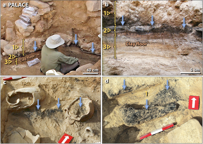
Destruction layer in the palace. (a) Photo of excavation in an exterior food preparation area of the palace. #1 marks MB II debris that was most likely deposited by post-fire erosion. #2 points to charcoal-rich 'dark layer' indicating a major fire in the palace. Contains fragments of plaster and limestone spherules. Blue arrows mark its top. #3 points to the cross-section of excavated clay flooring. (b) Close-up photo of the same palace sampling sequence as in panel 'a'. (c) Photo of broken pots with carbonized grains embedded in MB II 1.5-m-thick debris matrix, mostly composed of pulverized mudbrick and plaster fragments and limestone spherules. Debris matrix is found in the space between all palace walls. Note charcoal inside the broken pot. The end of a scale stick with 10-cm divisions is at upper left. (d) Charred palace roof timber surrounded by 1.5-m-thick charcoal-rich debris matrix of pulverized mudbrick. A scale stick shows 10-cm markings.
Full size image
In another test of organic carbon content, we added water to ~ 100 g of sediment for 10 contiguous samples from the palace and collected the float. Inspection by optical microscopy confirmed that the float from the destruction layer contained mostly charred organic material, e.g., soot, ash, charcoal, wood, and plant fragments at 1.7 wt.% of bulk sediment, while the layer beneath it contained 0.1 wt.%. The other 8 strata contained no detectable float.
Sedimentary soot was analyzed in one sample of the destruction layer from Field UB, located behind the palace. The sample was mostly silty, calcareous sand with no visibly apparent charcoal, wood, or textiles. It contained an average of 1.0 wt.% total organic carbon (TOC) with a high ratio of soot carbon to total organic carbon (soot/TOC), averaging 75.8% (range 55.7–95.8% in two aliquots). This high ratio in the destruction layer is consistent with intense biomass burning that converted most organic matter into soot via condensation of combustion-derived gases.
Diamond-like carbon (diamonoids)
Nanodiamonds and diamond-like carbon have been used as indicators of cosmic impacts, including at the Cretaceous-Paleogene boundary (K-Pg) at ~ 65 Ma29,30 and the Younger Dryas boundary (YDB) at 12.8 ka31. Kinzie et al.31 concluded that impact-related nanodiamonds and diamond-like carbon (DLC or diamonoids) are produced from the pyrolysis of carbon sources, e.g., vegetation and carbonate rocks that were pyrolyzed during high-temperature, high-pressure airburst/impact events. To search for nanodiamonds in TeH sediment, we followed the protocol of Kinzie et al.31, who used multiple reagents to remove all minerals except refractory, acid-resistant carbon.
In six samples of TeH bulk sediment from the temple (LS42J), we searched for, but were unable to detect the presence of nanodiamonds but did observe carbon atoms clustered into irregularly shaped plate-like clumps. Examination using bright-field high-resolution transmission electron microscopy (HRTEM) reveals short-range carbon structures, typically composed of less than 1–2 dozen atoms (Fig. 8). Analyses by transmission electron microscopy (TEM) and selected-area electron diffraction (SAD) indicate that the structures are composed of quasi-amorphous carbon that does not produce SAD patterns (Fig. 8c), even though organized, short-range structures are present (Fig. 8b). This material is commonly referred to as diamonoid or diamond-like carbon (DLC)31, representing the smallest unit observed in a diamond crystal lattice. These structures are nearly as hard as diamond and are stable at temperatures up to ~ 1000–1200 °C31. Diamonoids were observed in all samples investigated, but abundances peaked at ~ 3 ppm in the temple destruction layer. This value is > 3× higher than background concentrations that average 0.9 ppm (range 0.4–1.9 ppm) both above and below the destruction layer.
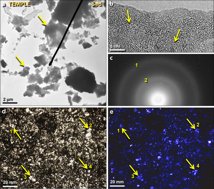
Diamonoids (diamond-like carbon) in temple sediment. (a) Transmission electron microscopy (TEM) image of clusters of amorphous diamonoids. (b) Bright-field high-resolution transmission electron microscopy (HRTEM) of acid-resistant residue showing the short-range ordering of carbon atoms. (c) Selected-area electron diffraction (SAD) of residue and grid film, confirming that the residue is amorphous carbon. (d) Photomicrograph of diamonoids showing white to clear material on black carbon SEM tab; (e) photomicrograph of the same area as in panel 'd' showing that the diamonoids luminesce at ~ 440 nm, typical of cubic diamonds.
Full size image
When viewed using optical microscopy, these nanocrystals appear clear to translucent white (Fig. 8d), as is typical of diamonoids and diamond-like carbon32, as distinguished from opaque, non-diamond forms of carbon that are commonly black or gray. When the same field of residue was exposed to ultraviolet light sources, the carbon-rich residue luminesced (Fig. 8e) at some of the characteristic luminescence bands for diamond, 365 nm (long-wave UV) and 440 nm33.
One fragment of melted pottery from the palace exhibits the results of the impact of a 30-µm-wide carbon-rich particle (Fig. 9). Using optical microscopy, the particle is whitish and translucent-to-clear, the same as the diamonoids extracted from sediment. SEM–EDS analyses indicate that this particle is an aggregate of hundreds of discrete plate-like amorphous carbon grains, along with a few micron-sized grains of Si, Ca, and Al oxides. The individual grains are anhedral with no apparent structure, resembling TEM images of TeH diamonoids.
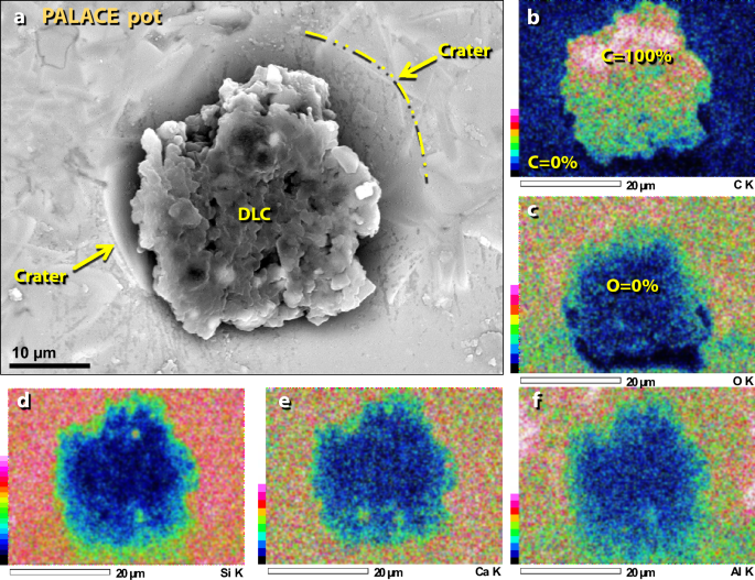
Diamond-like carbon embedded in pottery from the palace. (a) Pure carbon aggregate, likely a diamonoid cluster, is embedded in a crater on the melted surface of the pottery. (b)–(f) SEM–EDS elemental maps showing that the particle is composed of carbon with almost no oxygen or other elements; the object is embedded in the Ca–Al–Si pottery matrix.
Full size image
Discussion of diamonoids
Diamond-like carbon or diamonoids are found associated with extraterrestrial impact events34 but are also found in hydrocarbon deposits and coal34. Each diamonoid typically contains carbon atoms that are sp 3-bonded (i.e., 3 bonded carbon atoms), as in diamond, rather than with sp 2 bonding (i.e., 2 bonded carbon atoms), typical of graphite34.
Although diamonoids peak in the temple destruction layer, indicating likely exposure to high temperatures, they are also present at lower concentrations in all other layers. This may be due to the reworking of the nano-sized diamonoids, which are easily redeposited by wind and water.
The carbon-rich aggregate that is fused to the melted surface of the pottery is whitish-to-clear (Fig. 9), and so, we propose that this object is a cluster of diamonoids. The particle appears to have had sufficient velocity to produce a crater in the molten potsherd. If so, the velocity was low enough not to have shattered the low-mass, high-energy particle and yet, high enough to have pushed aside the viscous molten glass.
Melted construction materials
Melted pottery
Surface-melted potsherds were found about 15 m northeast of the palace complex in the destruction layer in Field UB (Fig. 10). These were associated with numerous unmelted potsherds within a sealed MB II context that is deeply buried in undisturbed sediment beneath ~ 2.5 m of Iron Age walls, indicating that melted potsherds were not redeposited from younger strata. Their MB II age was determined by seriation (pottery styles) and radiocarbon dating of associated materials, typically charred seeds and grains. The potsherds were mixed within a heavily churned debris matrix, containing charcoal, ash, pulverized mudbrick, potsherds, roofing materials, and fragments of limestone building plaster. No melted material was found anywhere in the city in younger or older layers, spanning ~ 3500 years, including from the Early Bronze Age (3300–2300 BCE), Late Bronze Age (1550–1200 BCE), Iron Age (1200–332 BCE, and Early Roman times (63 BCE-135 CE).
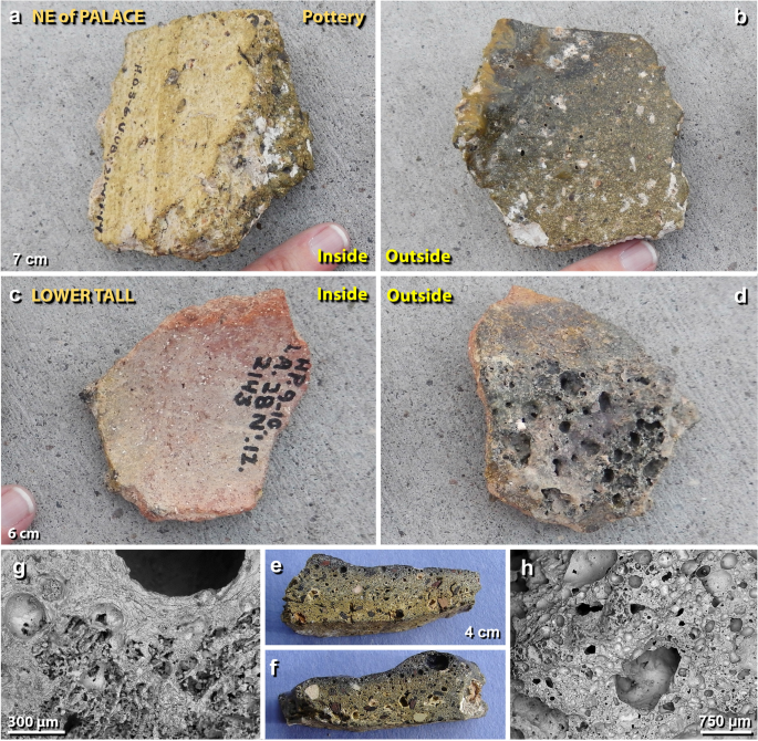
Melted pottery. (a) Photos of a 7-cm-wide potsherd from a broken storage jar from NE of the palace, showing unmelted inner surface and (b) the darker melted outer surface of the potsherd. The upper-left edge in panel 'b' is the outward-curved lip of a storage jar. (c) Potsherd of a 6-cm-wide storage jar from the lower tall, displaying an unaltered inner surface, and (d) the highly vesicular outer surface. (e)–(f) Photos of both edges of the sliced section of sherd in panels 'a' and 'b' above. (g)–(h) SEM images of the highly vesicular sliced surface of sherd in panels 'a' and 'b'.
Full size image
One melted potsherd analyzed from the Square 10JJ in the palace (Fig. 10a, b) came from the shoulder/neck transition of a wheel-made MB II storage jar. The sherd was constructed from tan-colored, gritty, sandy clay and has a maximum thickness of ~ 1 cm. The sliced edge shows that only the outer 2 mm of the sherd were altered to glass, while the next 4 mm of clay were darkened by thermal exposure but not melted; the inner 4 mm of the sherd matrix are unmelted (Fig. 10e, f). Photomicrographs and SEM images show that the outer surface of the potsherd is relatively smooth, glossy glass, indicating high-temperature melting and entrainment of porosity, followed by rapid quenching. The inside is unmelted. Most of the edges of the potsherd are highly vesicular (Fig. 10g, h), and once-molten clay drapes over some of the broken edges, suggesting that melting of the sherd took place following breakage. The inner portion of the sherd that is visible on the broken or sliced edges appears to be original unaltered clayey sand with few voids (Fig. 10f, g). On the interior surface of the potsherd, mineral inclusions are unmelted. On the other hand, most minerals embedded in the exposed or exterior surface of the potsherd exhibit significant melting during which the matrix was transformed into greenish, translucent glass.
Another melted potsherd came from the temple in the lower tall, closely associated with sherds of unmelted MB II pottery. One sherd (Fig. 10c, d) is part of a typical red clay pot. The average thickness of the sherd is 5 mm, but only the outside 2 mm of the sherd had been altered into a highly vesicular glass. The middle 1 mm of clay is darkened, presumably by thermal exposure but is not melted. The bottom 2 mm of clay retains their original red color and are unmelted. The curvature of the sherd shows that melting was limited to the outside of the pot's exterior or exposed surface. In SEM images, the edges of this sherd appear unmelted, while the outer surface is melted and highly vesicular, indicating exposure to high temperatures. Many minerals embedded in the surface are partially or fully melted, while most minerals contained within the matrix are unmelted.
SEM/Energy Dispersive X-Ray Spectroscopy (SEM–EDS, using a large spot size) and microprobe analyses of both sherds indicate similar compositions. They are dominantly composed of SiO2 at ~ 48.6 average wt.%; CaO at ~ 17.5 wt.%; and Al2O3 at ~ 15.0 wt.% (values for other oxides are provided in Supporting Information, Tables S4, S5). The Ca-rich matrices contain abundant crystals of plagioclase and pyroxene. The composition of the clay used to make the pottery is smectite (montmorillonite) with a high percentage of calcium hydroxide due to weathering of the abundant local limestone. When mixed with quartz as a binding agent, this type of clay was extensively used by regional cultures for centuries as the standard raw material for pottery.
Discussion of melted pottery, heating experiments
We investigated the melting point of TeH pottery by conducting heating experiments on unmelted pottery from the MB II destruction layer. First, we used Differential Scanning Calorimetry with Thermogravimetric Analysis (DSC-TGA). DSC measures the heat flow of a sample over a temperature range and TGA measures the weight change of a sample over the same temperature range. We observed a 32.7% weight loss between ~ 381 and 831 °C but with only an additional 0.5 wt.% weight loss after ~ 831 °C during heating to ~ 1400 °C (Supporting Information, Fig. S3b). This indicates that the powder gave off physically and chemically bound volatile materials (e.g., H2O and CO2) during the ramp-up to 831 °C, with minimal subsequent outgassing. During cooling, the sample showed no further weight change, as expected in an argon atmosphere. The DSC results demonstrated a large endothermic peak coinciding with the decomposition/weight loss of the sample during the temperature increase to ~ 831 °C. There was an increase in heat flow at ~ 1150 °C and again at ~ 1310 °C, suggesting exothermic reactions possibly due to the recrystallization of the phases present. The powdered pottery retained its crystalline, irregular granule morphology after DSC heating to 1400 °C, the maximum temperature achievable in this experiment. These results, therefore, indicate melted potteries were exposed to temperatures at TeH of > 1400 °C.
Independent studies show that the typical melting point of clay ranges from ~ 1200° to 1600 °C35. Using the average bulk analysis of the pottery of CaO at ~ 17.5 wt.%, SiO2 at ~ 48.6 wt.%, and Al2O3 at ~ 15.0 wt.%, the theoretical minimum melting point of the pottery is between 1300° and ~ 1500 °C, according to the CaO–Al2O3–SiO2 (CAS) ternary phase diagram36 (Supporting Information, Fig. S3a). These theoretical calculations are consistent with the heating experiment which showed no detectable melting at ~ 1400 °C.
To further investigate the melting point of pottery, we conducted laboratory experiments using an oxygen/propylene torch and thermocouple. After full exposure for ~ 2 min, one fragment of unmelted Ca-rich palace pottery began melting at ~ 1500° ± 25 °C (Supporting Information, Fig. S4). Although the temperature and heat flux were sufficient to melt a small area of the potsherd, the experiment was unable to duplicate the extensive melting observed on melted TeH potsherds. In addition, quartz grains embedded in the pottery remained unmelted. This result suggests that the maximum exposure temperature for the excavated melted potsherds was higher than 1500 °C and the flux rate was higher.
Remanent magnetism of melted pottery
Because storage pots had, at times, been placed on the roofs of buildings at TeH, we explored the possibility that the melted pottery and mudbricks may have been struck by lightning causing flash-melting. We used the same technique as in Moore et al.17 for measuring remanent magnetism, the magnetization remaining after Fe-rich materials cool while exposed to Earth's ambient magnetic field (i.e., geomagnetism37). Remanent magnetism can vary from fully magnetized, i.e., saturated, as may occur during lightning strikes, to fully demagnetized, i.e., desaturated.
Two samples of melted pottery from TeH were analyzed: TeH_VITPOT_1 at 20.6 g and TeH_VITPOT_2 at 113.5 g. The measurements of remanent magnetism in both samples were nearly the same. The results are consistent with the samples having cooled while exposed to Earth's normal geomagnetic field (Supporting Information, Fig. S5). They do not exhibit any evidence of intense magnetic fields generated during lightning discharges, meaning that it is highly unlikely that the TeH potsherds were melted by lightning strikes. For an example of the magnetization of rock by an electric discharge, see Kletetschka et al.38,39,40,41 and Wasilewski and Kletetschka42.
Melted mudbricks
MB II mudbricks in the TeH destruction layer are present in varying states of preservation. They are occasionally found whole or partially broken but typically are highly fragmented or pulverized. Both melted and unmelted mudbricks vary in color through shades of red, brown, gray, and black (Fig. 11). Because melted mudbricks are typically indistinguishable from melted sediment, which is mostly composed of pulverized mudbricks, for simplicity, we refer to all of this material as 'melted mudbricks'. The abundances of melted material spanned a wide range: ~ 0.6 g/kg along the ring road (Fig. 12a); ~ 0.1 g/kg in the temple (Fig. 12b); ~ 5 g/kg in palace location 7GG (Fig. 12c); and ~ 150 g/kg in palace room 7HH (Fig. 12d) (Supporting Information, Table S3). None was observed in the wadi.
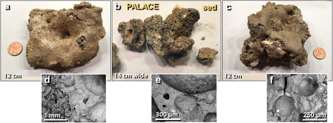
Melted mudbrick from the palace. (a) The upper surface of meltglass, showing non-vesicular 'skin'; (b) broken surfaces of meltglass displaying vesicular texture; (c) upper surface and broken faces of meltglass. Note large unmelted light-colored mineral inclusion. (d)–(f) SEM images of highly vesicular surfaces of broken meltglass. Note bright metallic inclusions in several vesicles.
Full size image

Meltglass: melted pottery, mudbrick, and roofing material. (a)–(d) Meltglass from 3 sites; no meltglass was found in the wadi and none was found above or below the destruction layer. Depths are in cm above or below the bottom of the destruction layer.
Full size image
On the upper tall, melted mudbricks were found in the MB II destruction layer within the palace, Field UA, in six different excavation squares. Typically, the thickness of melting is ~ 1–5 mm. Melted mudbricks (with melted pottery and roofing clay) were found ~ 2 m below the surface, mixed within a 30-cm-thick matrix of broken pottery and decomposed unmelted mudbrick. The destruction matrix also contained ash, charcoal, charred and unburnt roofing beams, charred and uncharred grains, and burned fabric and bedding. The density of mudbrick meltglass in the most concentrated pockets reached > 50% by volume, and in some cases, fractured chunks of melted material were found in pockets several meters in diameter and up to 30 cm thick. Between these pockets, the density trailed off to 10–15% by volume. The melted mudbrick fragments were typically surrounded by decomposed mudbrick and were rarely found with ash or charcoal, suggesting that they had melted before landing in their final locations.
A layer of melted mudbrick was often found overlain by ~ 15–30 cm of melted and unmelted roofing clay. Typically, this melted clay was many times more abundant than melted mudbricks. In a 12 m × 12 m part of Field UA, melted clay roofing material was covered by a variable thickness of up to 1 m of relatively homogeneous, decomposed-to-whole, unmelted mudbricks of the Late Bronze Age. Above this small LBA footprint, when present, the uppermost meters consisted of a matrix of decomposed mudbrick, broken Iron Age pottery, and architectural debris, none of which was melted.
Unbroken upper surfaces of the melted material are typically relatively smooth, and the broken surfaces are often highly vesicular, as shown in SEM images (Fig. 11d–f). The lower surfaces sometimes display partially fused sand grains. Optical microscopy and SEM imagery reveal that the broken interior surfaces typically contain mineral inclusions that are mostly unmelted, although some are partially melted. The outer melted surfaces often contain mineral grains that are partially to fully melted. Scratch testing showed that the melted material will scratch glass but not quartz, indicating a Mohs hardness of between 5.5 (glass) and 7 (quartz).
The composition of the meltglass (collectively, melted mudbrick and roofing material) closely matches that of the melted pottery, dominantly composed of SiO2 at 48.1 wt.%; CaO at 17. 2 wt.%; Al2O3 at 2.5 wt.%; and C at 14.1 wt.% (Supporting Information, Tables S4, S5). Phosphate percentages in melted mudbrick vary from 6 to 16 wt.%, and its presence can lower the melting point. The ternary phase diagram for the melted mudbrick shows a theoretical melting point between ~ 1300° to 1500 °C (Supporting Information, Fig. S3a).
Discussion of melted mudbricks
Some minerals (e.g., calcite (CaCO3) and soda ash (Na2CO3) present in the mudbricks and bulk sediment can act as fluxing agents to lower the equilibrium melting point. To investigate the fluxing effect at Abu Hureyra, Syria, Moore et al.17 conducted heating experiments on Ca–Al–Si bulk sediment that is geochemically similar to the sediment at TeH. Laboratory temperatures were increased from ~ 1100 to ~ 1850 °C in increments of 50–150 °C. Bulk sediment melted at ~ 1250 °C, establishing a likely minimum melting point for TeH melted mudbricks and sediment.
Melted roofing clay
Melted clay material is associated with MB II roofs and upper-story floors at TeH that were built using large wooden beams that spanned the mudbrick walls. These large beams were overlain by smaller wooden crossbeams, which were, in turn, covered with straw and leaves (Fig. 13a), topped with multiple layers of dried clay that were individually troweled flat and smooth. Melted roofing clay was associated with ash, charcoal, charred beams, and burned textiles, which suggests exposure to high-temperature fire. Most of the roofing clay displays imprints of original roof construction material, e.g., straw, plant stems, and leaves (Figs. 13, 14). Typically, the depth of melting is ~ 1–5 mm. SEM analyses indicate that most of the imprints also exhibit siliceous plant components, including phytoliths, parenchyma cells, stomata, and siliceous plant fibers, all appear to be fused into the roofing clay at high temperatures. Scratch testing indicated that the hardness of the plant-imprinted roofing clay was between 5.5 (glass) and 7.0 (quartz) on the Mohs scale.
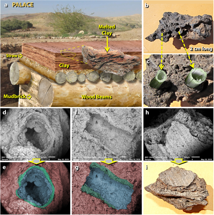
Melted palace roofing clay. (a) Artist's cutaway depiction of typical roof construction at TeH. The construction involved sequentially plastering multiple layers of clay (~ 10 cm or more in total thickness) over a bed of leaves and straw placed over wood beams. "Melted clay" inset at middle right is a photo of melted roofing clay still displaying horizontal layers of clay plaster. (b) Fragment of melted roofing clay exhibiting ~ 2-mm-diameter tubular holes left after incineration of straw; (c) artist's depiction, re-creating protruding straw before burning; (d) SEM image is the end-view of the hole left by burned straw embedded in roofing clay; (e) manually constructed EDS-based phase map of the same image, showing composition as determined by SEM–EDS; red represents melted clay matrix, green represents high-silica glass (60–90 wt.% SiO2) formed from melted silicified straw, and blue represents the silica-rich interior of the hole. (f) SEM image is the side-view of the imprint left by burned straw; (g) manually constructed EDS-based phase map of the same image, color-coded as in the previous example. (h) SEM image of leaf imprint into the clay roofing material, showing the ribbed structure of a leaf; (i) photomicrograph of the same object.
Full size image
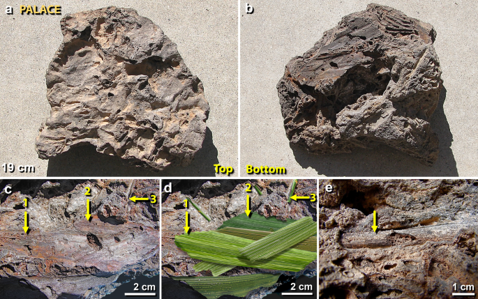
Plant imprints in melted roofing clay from the palace. (a) The upper surface of a 19-cm-wide piece of roofing clay, melted and distorted at high temperatures; (b) lower surface of the same object, showing imprints of silicified plant material; (c) closeup of the lower surface with numbered yellow arrows pointing to ribbed imprints of leaves pressed into the bottom of roofing clay (#1 through #3); (d) artist's depiction, re-creating possible leaf structures before combustion; (e) yellow arrow points not to a plant imprint, but rather to a cylinder-like silica-rich pyromorph of plant stem embedded in roofing clay. From the destruction layer in the palace (Field UA, Square 7GG).
Full size image
Discussion of melted roofing clay
Exposure to high temperatures is inferred to have vaporized the water and carbon from the plant material and then, fused the clay into hard vitrified masses. This process appears similar to that documented for proposed airburst/impact materials at Abu Hureyra, Syria17, and Dakhleh Oasis, Egypt43.
The clay imprints of siliceous plant material are inferred to have been made by biogenic hydrated silica (SiO2 ⋅H2O). Plants use dissolved silica from soils to produce Si-rich cell walls and connecting tissue that increases the plants' rigidity, toughness, and herbivore resistance44,45. After combustion, these decay-resistant siliceous structures retain their original morphologies17. This siliceous material can be freed from surrounding plant tissue by fire at ~ 450–550 °C but does not melt at such low temperatures46. Moore et al.17 reported laboratory experiments with an oxygen/propylene torch in which temperatures of > 1250 °C were required to fully melt siliceous plant material embedded in Ca–Al–Si meltglass.
Directionality of debris
During 15 field seasons at TeH, there have been extensive excavations of ~ 100 squares (each ~ 6 × 6 m in size) spread across the upper and lower tall. On TeH occupational surfaces older and younger than the MB II destruction layer, whole and broken pottery were nearly always found with all fragments confined to a small area that was their 'working space'.
In contrast, the destruction layer exhibits a distinct orientation pattern marking the distinct movement of objects across the MBA-age excavated floors. Out of about 2000 different vessels represented in the palace destruction matrix, most are fragmentary, and not a single one, smashed or otherwise, has been found in its 'working' place on a floor or other surface, and instead, nearly all pottery vessels were broken and strewn in a narrow SW-to-NE orientation spanning up to 10 m. On the rare occasions when intact or nearly-intact ceramic vessels were found, they were seldom found on the SW side of walls, but rather were protected on the NE side of walls, often tilted to the NE and embedded in the destruction matrix. For example, the excavators uncovered an MBA-age food preparation room in the palace with more than 150 separate pottery vessels (some shown in Fig. 15). Shattered MB II potsherds were strewn across the palace floors from SW to NE, nearly always located within the bottom ~ 20 cm of a churned-up debris matrix that ranged in thickness from 50 to 150 cm. Grains, such as barley, that had been stored in some of the pots, were also distributed from SW-to-NE interspersed among the trail of potsherds.
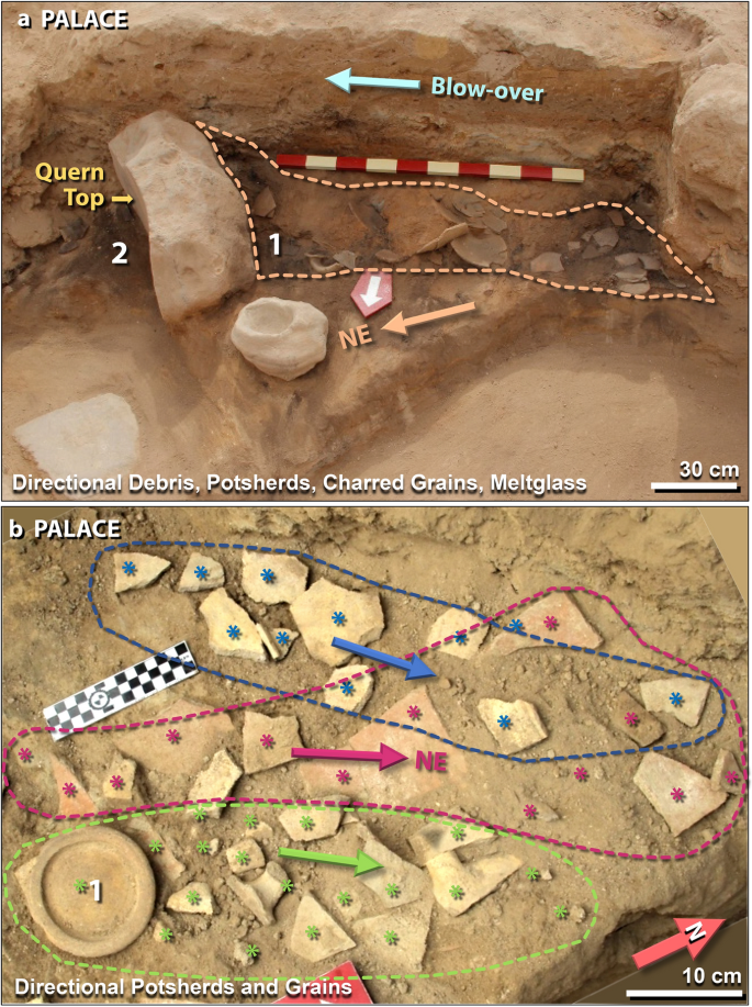
The directionality of mudbricks, potsherds, and grains. (a) 400-kg quern, at left, used for grinding grain, is tipped over with top towards NE. Image view spans ~ 2.5 m. Area #1 shows broken pottery and meltglass piled against quern from SW to NE (arrow). Area #2 contains charcoal, charred grains, ash, and mudbrick fragments, but no potsherds, suggesting that the quern shielded the floor to the NE. The area at the top labeled 'blow-over' is evidence that strong winds sealed the deposit with windblown laminated material that includes pulverized mudbrick, charcoal, ash, and fragments of white plaster. The draping of the blow-over indicates debris traveled from SW to NE. The scale stick is in 10-cm intervals. (b) Directional potsherds. Blue, red, and green asterisks (*) represent color-coded potsherds from three different pots. Arrows mark the motion of potsherds from SW to NE, spanning ~ 1 m. Area #1 represents the inverted bottom of the pot with its smaller fragments strewn to the left. Some pots contained charred grains also strewn in a SW-to-NE direction. Radiocarbon dates on charred grains confirm an age of ~ 1650 BCE (3600 cal BP).
Full size image
In another notable example, a distinctively decorated pot was found in pieces spread narrowly across ~ 6 m, with the majority of its decorated fragments concentrated against the SW-facing wall of the room. Broken potsherds from at least 50 separate vessels of all sizes have been found on this surface and all pieces were strewn in the SW-to-NE direction. Figure 15b shows three examples of shattered pots with potsherds strewn in narrow paths across > 60 cm in a SW-NE orientation. Before being excavated, they were embedded in pulverized mudbrick from the destruction layer.
This pattern of directionality was also observed for larger objects. Within the sealed, undisturbed MB II context of the palace, excavators uncovered a heavy saddle quern (weight: ~ 400 kg or 880#; dimensions: ~ 90 × 50 × 40 cm). Made of dense local stone and used for grinding grain, the quern was found toppled from its dirt pedestal and tipped on its side on the floor of a food preparation area (Fig. 15a). The geometric axis of the quern aligns with the SW-NE direction. Barley grains that had once been on top of the quern were found carbonized and strewn across the floor ~ 1 m to the NE between the overturned quern and the SW-facing wall, suggesting SW-to-NE movement (Fig. 15a). Radiocarbon dating of carbonized wood and grain from this floor confirms ~ 1650 BCE (~ 3600 ± 50 cal BP) as the date for the destruction event.
Discussion of directionality
An inferred sequence of events that produced the destruction layer (collectively the lower debris matrix, the blow-over above it, and the upper charcoal-rich dark layer) is shown in Fig. 16. Over a brief span of seconds, a high-velocity, debris-entrained shock wave arrived from the SW, demolished the mudbrick walls of the city, blew over the fallen walls, severely abrading (sand-blasted) the top surfaces, and deposited thin laminations of pulverized mudbrick, fragments of crushed building plaster, limestone spherules, ash, and charcoal, typically 20–30 cm thick (Fig. 16e). The wind demolished the portions of walls and ramparts that extended higher than several courses of mudbrick. Along interior walls, melted mudbrick, broken pottery, wall plaster, charred beams, and other interior debris were pushed against the SW-facing sides of walls that were typically 60–70 cm thick (Fig. 16c), filled the remaining space with pulverized debris (Fig. 16d), and blew the remainder off the tall to the NE. This sequence of fallen walls, capped by blow-over layers, appears to have occurred nearly instantaneously because there is no evidence of erosion or passage of time between the top dark layer, the blow-over layers, and the underlying debris matrix. Significantly, above the destruction layer, there is no evidence for extensive human occupation at TeH for ~ 600 years. Instead, gradual sediment erosion and redeposition buried the entire destruction layer. After that long hiatus, the city was only minimally rebuilt during the Iron Age and never returned to its former size and level of occupation.
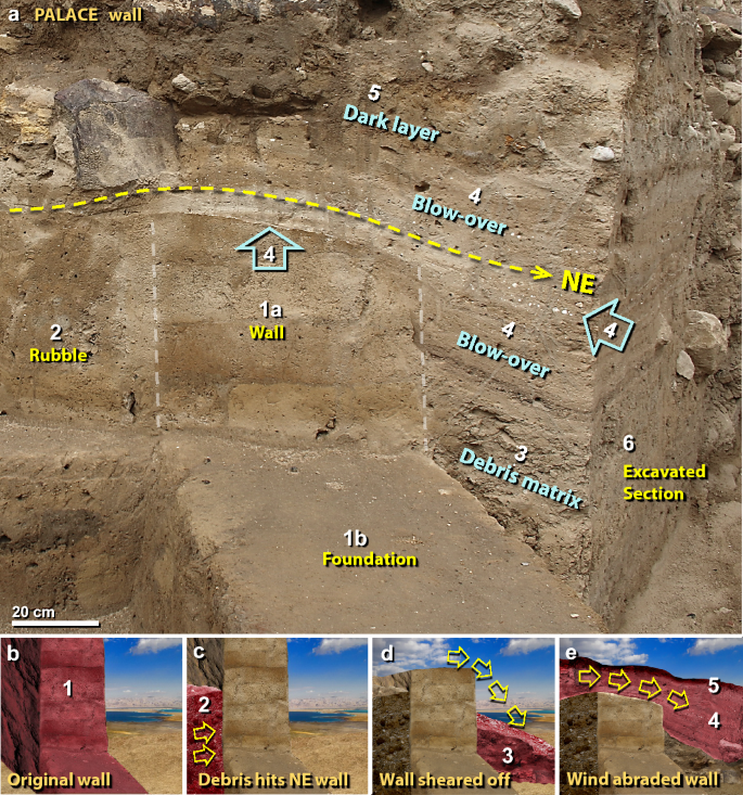
High-velocity effects. (a) Photo of an excavated section of the palace wall on upper tall. In the center are the lower courses of the mudbrick wall (#1a, between white dashed lines) and foundation (#1b). Yellow dashed line with arrow indicates wind direction of blow-over to NE. Also, note the lines of white fragments of broken plaster at two blue arrows (#4), where the curved wall top displays intense wind abrasion. At the right side of the image, #6 marks the limit of modern excavation. The sequence of wall destruction is illustrated in panels 'b' to 'e' below. (b) An artistic depiction, re-creating the pre-destruction mudbrick wall and foundation highlighted in red (#1). (c) Rubble in red (#2) was blown against the SW-facing side of the wall; material mainly consists of pulverized mudbricks and shattered potsherds. (d) Section of wall higher than several courses of mudbrick was demolished and blown to the NE to form the debris matrix (#3). (e) High-velocity winds blew from SW to NE (arrows), severely abrading the top of the wall, and burying it in debris. Winds produced the laminated 'blow-over' (#4), containing small pulverized mudbricks, fragments of white wall plaster, and limestone spherules stripped from interior walls. Settling on top, the 'dark layer' (#5) is mostly composed of charcoal and ash from the city-wide fires, along with post-destruction fine particulates.
Full size image
Evidence of directionality from SW to NE within buildings has been identified in ~ 100 excavated squares across the site. Directionality is indicated for up to six materials: (i) melted pottery, (ii) melted mudbricks, (iii) blow-over detritus, (iv) general building material, (v) seeds and grains, and (vi) potsherds. Notably, all excavated squares, including the palace, temple, and ring road (Fig. 17), display evidence of SW–NE-trending blow-over materials, primarily composed of thinly-laminated layers of pulverized mudbrick, ash, charcoal, and fragments of white plaster.
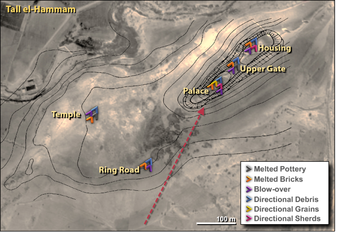
The directionality of debris across the entire TeH site. Color-coded arrows indicate the type and direction of six types of debris. Red dashed arrow and colored arrows mark the movement from SW to NE across excavations that span an area of ~ 58,000 m2 (~ 480 m long by up to ~ 240 m wide). Created by the authors using Adobe Photoshop CC2014 (adobe.com/products/photoshop.html).
Full size image
Following the destruction event, archeological evidence indicates that the city was only minimally rebuilt ~ 600 years later during the Iron Age. When that occurred, there is no apparent evidence that later inhabitants recycled surviving mudbricks for rebuilding the city. In any event, later structures are far too few to account for the massive number of missing mudbricks. Nearby cities were not rebuilt either, so no mudbricks from TeH could have been used for that purpose. Furthermore, the city foundations are sealed by pulverized mudbrick and charcoal that dates to ~ 1650 BCE throughout the city, indicating the destruction layer has remained undisturbed for > 3600 years until modern times. In summary, the evidence is consistent with the hypothesis that the city's mudbrick walls were pulverized by hypervelocity winds from a high-temperature event of cataclysmic proportions and the debris was blown off the tall to the NE.
High-pressure shock metamorphism
Shocked quartz at Tall el-Hammam
To further test the hypothesis that a cosmic airburst/impact event destroyed TeH, we searched for shocked quartz, one of the most commonly accepted cosmic impact indicators47,48,49,50. When quartz grains are exposed to shock compression during a cosmic impact event, they develop both irregular and regular microfractures, including planar fractures (PFs), short feather fractures (FFs), and/or planar deformation features (PDFs)51,52. Here, we refer to them collectively as 'shock lamellae'. Impact-shocked grains display one or more sets of shock lamellae that are aligned with quartz's crystallographic axes. Conversely, natural quartz has no visible crystallographic cleavage but may display randomly oriented non-parallel fractures.
We used multiple analytical techniques to examine quartz grains from the destruction layer in the palace (7GG) (Figs. 18, 19) and the temple (LS42K) (Fig. 19). We prepared two microscope slides, each containing ~ 2000 quartz grains that were thin-sectioned, polished, and etched with hydrofluoric acid (HF) (see Methods). Next, the slides were examined using optical microscopy to identify grains displaying potential lamellae; SEM–EDS was used to confirm the quartz composition and to image any visible lamellae; cathodoluminescence (CL) was used to investigate luminescence; and a universal stage, or U-stage, was used to investigate polarization and to record the azimuth and inclination of lamellae49,53,54. Finally, the crystallographic axes were plotted with the ANIE indexing program55 and compared to those of quartz (Fig. 20).
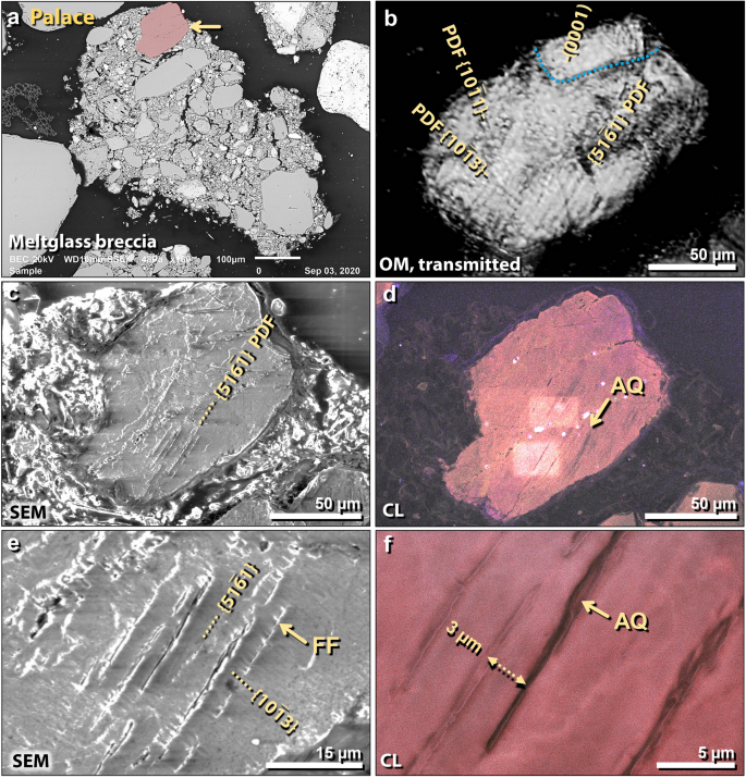
Shocked quartz grain from TeH palace. (a) SEM image of a 750-µm-wide fragment of meltglass breccia from the palace, containing melted and partially melted grains surrounded by Ca–Al–Si meltglass. Shocked quartz grain in red at arrow; other grains are not shocked. (b) Transmitted light photomicrograph using an optical microscope (OM); 155-µm-wide HF-etched quartz grain is same as in panel 'a'. Lamellae are labeled as Miller-Bravais indices (hkil) (ANIE program55). Three sets in lower crystallite are all closely-spaced PDFs crossing the entire crystallite. Blue dotted line marks the boundary of one crystallite in polycrystalline grain, containing only one set of lamellae, the (0001) plane with its pole parallel to the c axis. (c) SEM image of same HF-etched grain displaying visible lamellae, which excludes them as tectonic lamellae. (d) SEM-CL image of same grain showing multiple closely-spaced non-luminescent lamellae (black), indicative of amorphous quartz (AQ). (e) Close-up SEM image of same grain, showing visible lamellae, all of which display short-range feather features (FF) that form at ≥ 7 GPa. (f) SEM-CL close-up image, showing black non-luminescent centers of lamellae, indicative of amorphous quartz. Lamellar spacing is ~ 3–5 µm.
Full size image
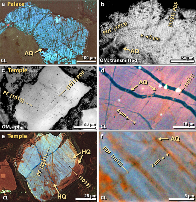
Shocked quartz grains. (a) SEM-CL image of 510-µm-wide grain from the palace. Border of grain and isolated interior regions are non-luminescent black under CL, indicating the presence of melted (amorphous) quartz (AQ). The unshocked quartz body is blue. (b) Transmitted light photomicrograph of same grain under crossed polars. Dark portions of grain are isotropic, indicative of amorphous melted quartz. Two closely spaced PDFs (~ 3 µm apart) are shown. (c) Epi-illuminated photomicrograph of shocked quartz grain from the temple. Two sets of lamellae are labeled; one is a PDF and one a wider-spaced PF. (d) SEM-CL close-up image, showing one set of black non-luminescent lamellae. Irregular black non-luminescent areas at arrows are amorphous quartz bands (AQ) that are isotropic in optical microscopy but not evident using SEM. Two lamellae have 4-µm spacing. (e) SEM-CL image of polycrystalline shocked quartz grain from the temple. Crystallites are marked by blue dotted lines. Two sets of lamellae are indicated, one confined to each crystallite. Large areas of grain appear black and red under CL, suggesting that portions of the exterior and interior of the grain melted and some recrystallized. The unshocked quartz body is blue. (f) SEM-CL image of grain in panel 'e'; displays red lamellae with black centers, indicating a mix of amorphous quartz (black; AQ), healed quartz (red), and unaltered quartz matrix (blue). Two lamellae are ~ 2 µm apart.
Full size image
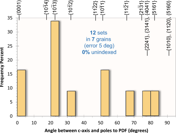
Sets of lamellae in shocked quartz grains. 7 TeH grains/crystallites display 12 sets of lamellae in 5° bins; no lamellae were unindexed. Two grains have a set of lamellae (0001) with its pole parallel to the c axis.
Full size image
The results show that an average of ~ 1 in 800 TeH quartz grains (n = 7 crystallites in 5 grains) display shock lamellae, ranging in thickness from < 1–2 µm with an inter-lamellar spacing of ~ 1–10 µm with most lamellae in the 2–5-µm spacing range. For all grains, most shock lamellae are discontinuous and do not fully extend across any given quartz grain. Most lamellae appear parallel to sub-parallel, and some are straight, but others appear curved, all of which have been reported at known impact sites, such as Meteor Crater, AZ47. In particular, the Charlevoix crater displays shocked grains with curved lamellae, deformation bands, micro-fractures, planes commonly oriented to (0001), and serrated (stair-step) plane boundaries56, all of which are observed at TeH. See Table 2 for details. Two grains display one set of lamellae oriented along the basal plane (0001); one crystallite has 3 sets of lamellae; 3 grains/crystallites display two sets; and 3 display one set of lamellae each. Note that for the 2 single-set grains that are sub-parallel to the c-axis, the indexing results are equivocal and only estimated because there is no uniquely measurable azimuthal relationship within each grain. Even so, the results are consistent with the relationship between the c-axis and the indexed planes.
Full size table
Optical microscopy and SEM imaging show that the shock lamellae commonly display asymmetry, the condition in which one side of a lamella appears darker and the other side brighter57. This difference is attributed to higher values on the bright side for density, refractive index, and/or birefringence57. Asymmetry is apparent for all shocked quartz grains from both the palace and temple. SEM imaging detected feather fractures (FFs) in one grain from the palace (Fig. 18e). These are narrowly spaced, short, parallel-to-subparallel lamellae that typically branch off other lamellae at ~ 50–60° angles and form at pressures ≥ 7 GPa51,58. Under crossed polars, 5 of 7 grains display mosaicism, a strongly mottled extinction pattern, and 2 of 7 grains display "undulose extinction," wavy extinction patterns oriented perpendicular to the direction of lamellae.
The cathodoluminescence results revealed that the quartz lamellae are either non-luminescent black (indicative of amorphous quartz59,60,61) or red (indicative of quartz that has crystallized, or 'healed'59,60,61). The unshocked body of the quartz grain typically appears blue. Further inspection of the non-luminescent lamellae using crossed polarizers on an optical microscope confirmed that material in some lamellae is isotropic, consistent with amorphous quartz47. Tectonic lamellae, i.e., ones that develop from slow strain along fault lines, commonly luminesce in blue or red wavelengths59,61, allowing for differentiation from impact-shocked quartz. One example from TeH is shown in Supporting Information, Fig. S6.
U-stage measurements show that all five quartz grains display crystallographically oriented microfractures, planar fractures (PFs), feather features (FFs), and/or planar deformation features (PDFs), all of which are characteristic of impact-related shock metamorphism51,61. Altogether, the 7 TeH quartz grains/crystallites match 17 of 17 distinguishing characteristics of classic impact-shocked quartz (see Table 2), but match few characteristics of tectonically-shocked quartz. We also investigated quartz grains from two samples above and below the destruction layer in both the palace and the temple and observed tectonically-shocked quartz but no shock lamellae in ~ 2000 quartz grains from each sample.
Discussion of shocked quartz
Planar microstructures (PFs) form at relatively low shock pressures (approximately ≥ 5 GPa)49 and involve only partial, localized alteration of the quartz grain. PFs are typically 5–10 μm wide and spaced 15–20 μm or more apart. Planar deformation features (PDFs) form at approximately ≥ 8 GPa and involve the transformation of crystalline quartz to an amorphous phase along lamellae50. PDFs are narrow (typically < 2–3 μm wide) and more closely spaced (typically 2–10 μm) than PFs, as are most lamellae in TeH shocked grains. PDFs are typically straight and parallel and are most commonly found in large impact craters, such as the Ries Crater in Germany and Popigai Crater in Russia61. However, at low shock pressures, PDFs may appear chaotic, subparallel, and often curved due to thermal alteration, as is evident at smaller impact sites such as Meteor Crater in Arizona and the Wabar Crater in Saudi Arabia47.
Basal plane lamellae (0001) are common at low shock levels of > 5 GPa and < 10 GPa48,49 but are rarely observed at higher impact shock levels of > 10 GPa49. Two of the 7 TeH shocked quartz grains/crystallites display (0001) planes, consistent with low shock conditions. At high pressures, the lamellae in shocked quartz often are very straight and parallel and extend from edge to edge of grains. However, at lower pressures, lamellae typically extend discontinuously across grains, as occurs in all five TeH grains, consistent with low shock conditions.
Known shocked quartz grains, when observed using optical microscopy and SEM imagery, are often decorated with lines of sub-micron-diameter bubbles. These decorations are considered to have 'healed' by slow reversion of amorphous quartz to crystalline quartz (e.g., in Vredefort crater61) and the resultant exsolution of water47,54. All shocked quartz grains at TeH display decorations.
In geologically old shocked quartz grains, shock lamellae are commonly discontinuous across grains and are decorated with micron-sized bubbles. However, the same result can occur from rapid, high-temperature, post-shock alteration during the impact event47. At TeH, the shocked quartz grains are inferred to have resulted from low-grade shock metamorphism that rapidly healed from thermal alteration during the impact event.
Shock metamorphism by a cosmic impact is the most likely explanation, but we also considered other processes that can produce lamellae in quartz.
- (i)
Shock lamellae can form during lightning strikes. However, these only form within a few microns of the grain edge, unlike impact-related shock lamellae that are found across the interior of grains. Lightning-produced lamellae also are more closely spaced (< 0.33 μm) and do not form along the (0001) plane62, as some do at TeH. These three characteristics are unlike those observed at TeH and eliminate lightning as a likely source of TeH shocked quartz grains.
- (ii)
Non-impact deformation lamellae can be produced by tectonically-induced pressures associated with faults, such as the Rift Zone near TeH. However, such lamellae are not oriented along the (0001) plane53,61, and instead, they commonly vary by ± 10°–30°. Tectonic forces produce slow-strain deformation that creates lamellae with the appearance of twisted ribbons but do not contain amorphous quartz61,63. SEM analyses of HF-etched grains allow for unambiguous visual distinction between glass-filled PDFs and glass-free tectonic lamellae, which are not visible on the surface of sectioned grains61,63. In addition, tectonic lamellae often appear blue in CL imagery and never black61. This eliminates tectonism as the source of the lamellae in all TeH quartz grains based on this criterion.
- (iii)
Several conclusive tests on these grains have enabled us to positively differentiate impact-shocked quartz from those that were tectonically-shocked. (a) The lamellae in known impact-shocked grains are crystallographically aligned, as at TeH, but unlike tectonic grains. (b) Impact-shocked lamellae are visible in SEM imaging and with epi-illumination using optical microscopy, indicating the presence of amorphous quartz, as at TeH and unlike in tectonic grains. (c) Impact-shocked lamellae are often non-luminescent (black) under CL imaging, as with TeH grains and unlike tectonic grains.
- (iv)
Lamellae in quartz can be produced artificially under laboratory conditions. Most such lamellae are oriented 45° to the c axis but some are parallel. This mechanism is not relevant to TeH, where the sample deposits are deeply buried and sealed from potential modern contamination.
- (v)
Shock lamellae can form in aboveground and underground atomic bomb blasts64, but no atomic detonations have occurred at TeH.
- (vi)
Shocked quartz is traditionally accepted as an indicator of a hard impact with Earth's surface, and so another possibility is a crater-forming impact, either at 1650 BCE or during a much older event. However, no shocked quartz grains were found above or below the destruction layer in the palace or the temple, making it likely that they date to 1650 BCE and unlikely that they result from an older or younger impact event. No contemporary crater has yet been identified, but a hypothetical crater of only a few tens of meters in diameter could have been created. If so, such a small crater may have been rapidly buried by wind action and/or overbank flooding from the Jordan River and thus, no longer be visible.
- (vii)
Finally, the most likely scenario is that the shock lamellae resulted from exposure to high pressures and high temperatures during a Tunguska-like cosmic airburst. In addition, when incoming bolides detonate at altitude, they can burst into numerous meters-wide fragments that strike the ground to form small transient craters, generating enough energy to create shocked quartz.
Based on the evidence, we conclude that TeH shocked quartz grains were ejected from ground zero (either under the airburst or in a crater) as distal ejecta and diluted by much higher numbers of non-shocked detrital grains. These shocked grains are a mixture of low-grade impact-related sub-planar microfractures, planar features (PFs), feather features (FFs), and planar deformation features (PDFs), most likely formed at ~ 5–10 GPa (50 k to 100 k standard atmospheres). Most TeH shocked grains have discontinuous lamellae that are partially healed due to simultaneous exposure to high pressures and high temperatures. We infer that this shock metamorphism occurred either during one or more small crater-forming impacts or airbursts within ~ 5–10 km of the city.
Shocked quartz grains from known airbursts
We also conducted investigations on three other airburst events to better understand the proposed TeH cosmic impact event. The first event, the Tunguska cosmic airburst, occurred above Siberia in 190865, estimated at ~ 10–30 megatons of TNT equivalent at an altitude of 5–15 km. Second, the Trinity atomic bomb was detonated at an altitude of 40 m in New Mexico in 194564, estimated at 22 kilotons of TNT equivalent. Third, two Russian atomic bombs were detonated at an identical location in Kazakhstan. Joe-1 (RDS-1) in 1949 is estimated at 20 kilotons TNT equivalent at 30 m elevation66, and Joe-4 (RDS-6) in 1953 is estimated at 400 kilotons at an altitude of 400 m66. Samples included an undifferentiated mix of materials from both detonations.
We searched for potential shock lamellae in grains in ~ 2000 thin-sectioned quartz grains from each of the three sites and observed approximately 1 shocked quartz grain per 500–1000 grains, similar to the results for TeH. At all three sites, a small number of shocked quartz grains appear to have been ejected from ground zero and mixed with numerous unshocked detrital grains. As with impact-related PDFs, the lamellae commonly appear as one or more sets that are closely spaced (2–10 µm), narrow (< 2 µm), and range from curved to straight and parallel to subparallel (Fig. 21). The lamellae in grains from all of these sites match 17 features of impact-shocked quartz (Table 2). Most importantly, the TeH grains pass four main tests that confirm impact-shocked lamellae and contra-indicate tectonic lamellae: (i) they are crystallographically aligned; (ii) some are parallel to the c axis; (iii) all are visible in SEM imaging and epi-illumination, indicating the presence of amorphous quartz; and (iv) all are non-luminescent (black) or red under CL imaging.
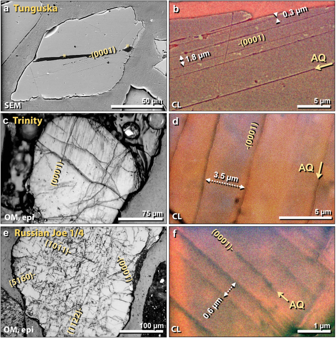
Shocked quartz from known airbursts. (a) SEM image of 140-µm-wide shocked quartz grain from Tunguska airburst. Discontinuous lamellae formed along the (0001) plane. (b) Close-up SEM-CL image of same grain as in panel 'a'. Lamellae spacing ranges from ~ 0.3 to 5 µm. Black lamellae indicate amorphous quartz (AQ). (c) Epi-illumination photomicrograph of 240-µm-wide shocked quartz grain embedded in trinitite that was ejected ~ 400 m from ground zero of the Trinity detonation. Discontinuous, sub-planar, sub-parallel lamellae are oriented along the (0001) plane. (d) Close up SEM-CL image of same grain as in panel 'c'. Lamellae spacing ranges from ~ 2.5 to 6.5 µm. Black lamellae indicate amorphous quartz (AQ). (e) Epi-illumination photomicrograph of 520-µm-wide shocked quartz grain from Russia's Joe-1/4 nuclear detonations; displays discontinuous sub-planar, sub-parallel micro-fractures and lamellae, just as reported for impact-shocked grains in the Charlevoix crater56. There are four sets of lamellae, one of which is oriented parallel to the (0001) plane. (f) Close up SEM-CL image of same grain as in panel 'e'. Lamellae spacing ranges from ~ 0.3 to 1.3 µm. Black lamellae indicate amorphous quartz (AQ).
Full size image
Discussion of shocked quartz in airbursts
In a previous study, shocked quartz was reported at Tunguska a few miles from ground zero67 but has been disputed58. To our knowledge, this is the first study to report shocked quartz at the site of the Joe-1/4 detonations. In addition, it has been reported at the Trinity site64,68, where Eby et al.64 concluded that Trinity shocked quartz had been exposed to pressures of at least 8 GPa and temperatures of > 1600 °C for a duration of 14–20 s with a maximum fireball temperature of > 8400° K for ~ 3 s.
A previous hypothesis explains how shock lamellae might form in a cosmic airburst, such as Tunguska. Kletetschka et al.69 proposed that when unconsolidated surface sediments containing quartz grains are struck by the atmospheric shock wave from an airburst, if the velocity exceeds 7 km/s, the elastic limit of quartz, then shock lamellae develop. Quartz grains in surface sediments typically are only minimally shocked, often with only one set of lamellae.
The Trinity detonation at an altitude of ~ 40 m above the surface was much lower than for Tunguska. In addition, the energy released was less than for a Tunguska-class event, but even so, it produced shocked quartz. For Joe-1/4, the detonation altitude of 400 m was lower than for Tunguska and the energy yield was less, but shocked quartz also was produced. These atomic tests support an important finding of this investigation and previous ones64,67: shock metamorphism can occur during an airburst in the absence of a ground impact, rather than, as is commonly accepted, only during ground impacts of sufficient magnitude to form a crater. Our evidence suggests that the lamellae observed in TeH quartz formed during a cosmic airburst under conditions similar to those during the Tunguska airburst and the aerial atomic detonations.
High-temperature melted minerals
Melted quartz grains
Crystalline quartz melts between 1670 °C (tridymite) and 1713 °C (cristobalite), and because quartz is pervasive and easily identified, melted grains serve as an important temperature indicator. At TeH, we observed that unmelted potsherds displayed no melted quartz grains, indicating exposure to low temperatures. On the other hand, most quartz grains on the surfaces of pottery, mudbricks, and roofing clay exhibited some degree of melting, and unmelted quartz grains were rare. Nearly all quartz grains found on broken, unmelted surfaces of potsherds were also unmelted. On melted pottery and mudbricks, melted quartz has an estimated density of 1 grain per 5 mm2.
Melted quartz grains at TeH exhibit a wide range of morphologies. Some show evidence of partial melting that only melted grain edges and not the rest of the grain (Figs. 22, 23). Others displayed nearly complete melting with diffusion into the melted Ca–Al–Si matrix of pottery or mudbrick (Fig. 22). Melted quartz grains commonly exhibit vesiculation caused by outgassing (Figs. 22, 23), suggesting that those grains rose above quartz's melting point of ~ 1713 °C.
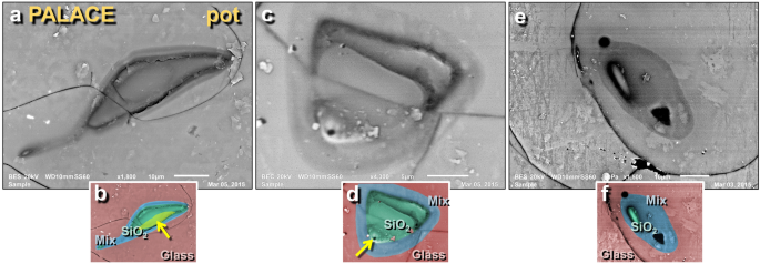
SEM images of melted quartz grains on melted potsherd from the palace. (a) Highly melted quartz grain from the upper surface of melted pottery; shows flow lines of molten quartz in darker 'neck' at upper right; (b) manually constructed EDS-based phase map showing 100% quartz grain (green) embedded in Ca–Al–Si matrix of melted pottery (red); blue marks mixing zone between SiO2 and matrix at approximately > 1713 °C, the melting point of quartz. Yellow arrow points to area depleted in oxygen, indicating high-temperature transformation to elemental Si mixed with melted SiO2. (c) Highly melted quartz grain; (d) manually constructed EDS-based phase map showing diffusion/mixing zone in blue with arrow pointing to bubble, indicating outgassing as grain reached temperatures above its melting point. (e) Quartz grain that has almost completely melted; (f) manually constructed EDS-based phase map showing the small remnant of a melted quartz grain (green) with a wide mixing zone (blue).
Full size image
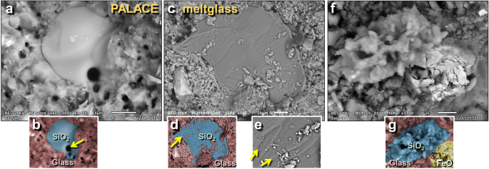
SEM images of melted quartz grains on melted mudbrick from the palace. (a) Highly melted quartz grain; (b) manually constructed EDS-based phase map indicates center is pure SiO2 surrounded by melted mudbrick. Arrow points to vesicles indicating outgassing as grain temperature rose above ~ 1713 °C, the melting point of quartz. (c) The surface of a flattened quartz grain showing flow marks toward the upper right. High temperatures are required to lower the viscosity sufficiently for quartz to flow. (d) Manually constructed EDS-based phase map with an arrow pointing to vesicles indicating outgassing at high temperatures. (e) Close up of grain in panel 'c' showing flow marks (schlieren) at arrows. (f) Shattered, melted quartz splattered onto mudbrick meltglass; (g) manually constructed EDS-based phase map indicating that the blue area is SiO2; the yellow area is a shattered, thermally altered Fe-oxide grain.
Full size image
An SEM–EDS elemental map of one melted grain showed that the quartz had begun to dissociate into elemental Si (Fig. 22b). Another grain (Fig. 23c–e) displayed flow marks consistent with exposure to temperatures above 1713 °C where the viscosity of quartz falls low enough for it to flow easily. Another SEM–EDS analysis confirmed that one agglutinated mass of material is 100 wt.% SiO2 (Fig. 23f, g), suggesting that this polycrystalline quartz grain shattered, melted, and partially fused again.
Discussion of melted quartz
Moore et al.17 reported that during heating experiments, many quartz grains < 50-µm-wide exhibited partial melting at as low as 1300 °C, but larger grains > 50-µm-wide remained visually unaltered up to ~ 1700 °C. By 1850 °C, all quartz grains fully melted. These experiments establish a particle-size dependency and confirm confirmed the melting point for > 50-µm-wide TeH quartz grains between ~ 1700–1850 °C. Melted > 50-µm-wide quartz grains on the surfaces of melted pottery and mudbrick from the TeH destruction layer indicate exposure to these unusually high temperatures > 1700 °C.
Previously, Thy et al.70 proposed that glass at Abu Hureyra did not form during a cosmic impact, but rather, formed in biomass slag that resulted from thatched hut fires. However, Thy et al. did not determine whether or not high-temperature grains existed in the biomass slag. To test that claim, Moore et al.17 analyzed biomass slag from Africa and found only low-temperature melted grains with melting points of ~ 1200 °C, consistent with a temperature range for biomass slag of 1155–1290 °C, as reported by Thy et al.71. Upon testing the purported impact glass from Abu Hureyra, Moore et al.17 discovered high-temperature mineral grains that melt in the range of 1713° to > 2000 °C, as are also found in TeH glass. These test results suggest that the melted glass from Abu Hureyra must have been exposed to higher temperatures than those associated with fires in thatched huts. Because of the presence of high-temperature minerals at TeH, we conclude that, as at Abu Hureyra, the meltglass could not have formed simply by burning thatched huts or wood-roofed, mudbrick buildings.
Melted Fe- and Si-rich spherules
The presence of melted spherulitic objects ("spherules") has commonly been used to help identify and investigate high-temperature airburst/impact events in the sedimentary record. Although these objects are referred to here as "spherules," they display a wide range of other impact-related morphologies that include rounded, sub-rounded, ovate, oblate, elongated, teardrop, dumbbell, and/or broken forms17,72,73,74,75,76,77,78,79,80,81,82. Optical microscopy and SEM–EDS are commonly used to identify and analyze spherules and the processes by which they are formed. Care is needed to conclusively distinguish high-temperature spherules produced by cosmic impacts from other superficially similar forms. Other such objects that frequently occur in sediments include anthropogenic spherules (typically from modern coal-fired power plants), authigenic framboids (Supporting Information, Fig. S7), rounded detrital magnetite, and volcanic spherules.
Spherules in TeH sediment were investigated from stratigraphic sequences that include the MB II destruction layer at four locations: palace, temple, ring road, and wadi (Fig. 24). For the palace (Field UA, Square 7GG), the sequence spanned 28 cm with 5 contiguous samples of sediment ranging from 3-cm thick for the MB II destruction layer to 13-cm thick for some outlying samples. In the palace, 310 spherules/kg (Fig. 24d) were observed in the destruction layer with none found in samples above and below this layer. For the temple (Field LS, Square 42J), 5 continuous samples spanned 43 cm and ranged in thickness from 6 to 16 cm; the MB II layer contained ~ 2345 Fe- and Si-rich spherules/kg with 782/kg in the sample immediately below and none at other levels (Fig. 24c). Six contiguous samples from the ring road (Field LA, Square 28 M) spanned 30 cm with all 5 cm thick; the MB II destruction layer at this location contains 2150 spherules/kg with none detected in younger or older samples (Fig. 24b). Five discontinuous samples from the wadi spanned 170 cm, ranging from 10-cm thick for the destruction layer up to 20-cm thick for other samples; the MB II destruction layer at this location contained 2780 spherules/kg with none in samples from other levels (Fig. 24a, Supporting Information, Table S3). Notably, when melted mudbrick from the ring road was being mounted for SEM analysis, numerous loose spherules were observed within vesicles of the sample, confirming a close association between the spherules and meltglass. At all four locations, the peaks in high-temperature spherule abundances occur in the MB II destruction layer dating to ~ 1650 BCE.
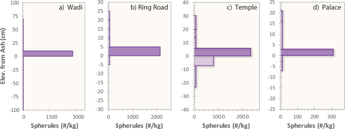
Spherule abundances. (a)–(d). Number per kg for Fe- and S-rich spherules from 4 locations. Depths are in cm above or below the bottom of the destruction layer.
Full size image
SEM images of spherules are shown in Figs. 25, 26, 27 and 28, and compositions are listed in Supporting Information, Table S4. The average spherule diameter was 40.5 µm with a range of 7 to 72 µm. The dominant minerals were Fe oxides averaging 40.2 wt.%, with a range of up to 84.1 wt.%; elemental Fe with a range of up to 80.3 wt.%; SiO2 averaging 20.9 wt.%, ranging from 1.0 to 45.2 wt.%; Al2O3 averaging 7.8 wt.% with a range of up to 15.6 wt.%; and TiO2 averaging 7.1 wt.% with a range of up to 53.1 wt.%. Fourteen spherules had compositions > 48 wt.% of oxidized Fe, elemental Fe, and TiO2; five spherules contained < 48 wt.% Fe and Ti; and two had > 75 wt.% Fe with no Ti. Eight of 23 spherules analyzed contained detectable levels of Ti at up to 53.1 wt.%.
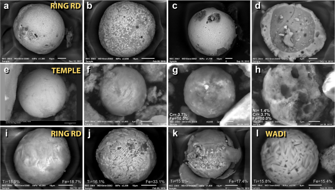
SEM images of mostly silica-rich spherules from TeH. (a)–(d) Representative spherules from the ring road on the lower tall. SEM images of iron-rich spherules. (e)–(f) Fe-rich spherules from the temple complex. (g) temple spherule containing ~ 3.7 wt.% Cr. (h) Broken, vesicular spherule from temple containing 1.4 wt.% Ni and 3.7 wt.% Cr. SEM images of titanium-rich spherules. Ti content of these ranges from 18.9 to 1.2 wt.%, averaging 10.7 wt.%. (i)–(k) Spherules from the ring road. (l) Spherule from the wadi site.
Full size image
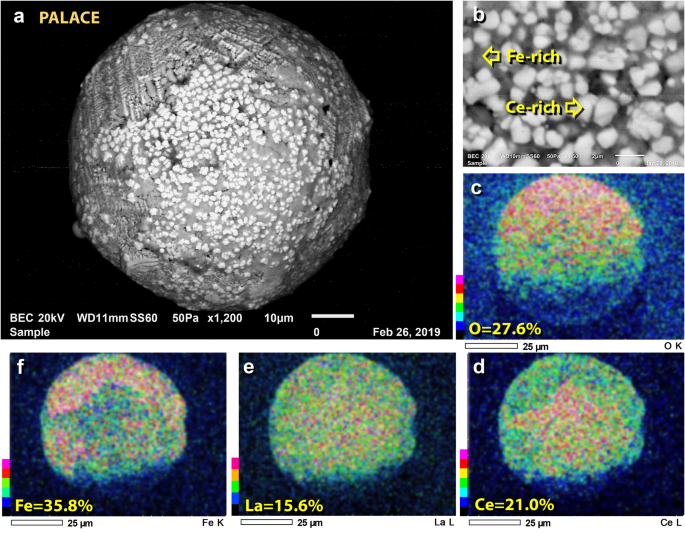
SEM image of rare-earth (REE) spherule. (a) REE-rich 72-µm-wide spherule from the palace, dominantly composed of Fe, La, Ce, and O. (b) Close up of REE blebs found on the spherule. (c)–(f) SEM–EDS elemental maps showing composition. La = 15.6 wt.% and Ce = 21.0 wt.%. Ce is enriched over Fe and La in the middle part of the spherule, as seen in panels 'd' through 'f'.
Full size image
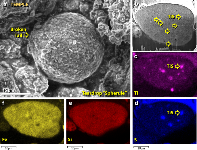
SEM images of a spherule mainly composed of Fe and Si. (a) Fe–Ti-rich 54-µm-wide spherule from the palace. Spherule displays a protrusion to the left, suggesting aerodynamic shaping when molten, after which the tail detached. (b) A focused ion beam (FIB) was used to section the spherule, revealing inclusions of wassonite or titanium sulfide (TiS; yellow arrows) that are lighter-colored than the matrix. (c)–(f) Color-coded SEM–EDS elemental maps, showing the distribution of Ti, S, Si, and Fe and the location of the TiS grains. The spherule is dominantly composed of Fe and Si with minor amounts of Ti and S found in TiS inclusions.
Full size image

Fe-rich spherules embedded in meltglass. (a) Optical photomicrograph of a 167-µm-wide piece of meltglass with embedded Fe-rich spherules. (b) SEM image of same grain as in panel 'a'. Melted quartz grain (Qtz) is embedded in Ca–Al–Si-rich matrix, which has the same composition as melted mudbrick. (c) SEM close-up image of the boxed area and panel 'b', showing splattered Fe-rich spherule.
Full size image
Two unusual spherules from the palace contain anomalously high percentages of rare-earth elements (REEs) at > 37 wt.% of combined lanthanum (La), and cerium (Ce) (Fig. 26), as determined by preliminary measurements using SEM–EDS. Minor oxides account for the rest of the spherules' bulk composition (Table S1).
One 54-µm-wide sectioned spherule contains titanium sulfide (TiS) with a melting point of ~ 1780° C. TiS, known as wassonite, was first identified in meteorites (Fig. 27) and has been reported in impact-related material17,81,83. However, TiS sometimes occurs as an exsolution product forming fine networks in magnetite and ilmenite and can be of terrestrial origin.
One unusual piece of 167-µm-wide Ca–Al–Si meltglass contains nearly two dozen iron oxide spherules on its surface (Fig. 28). The meltglass contains a completely melted quartz grain as part of the matrix (Fig. 28b). Most of the spherules appear to have been flattened or crushed by collision with the meltglass while they were still partially molten (Fig. 28c).
Discussion of spherules and meltglass
Melted materials from non-impact-related combustion have been reported in multiple studies. Consequently, we investigated whether Ca-, Fe-, and Si-rich spherules and meltglass (mudbrick, pottery, plaster, and roofing clay) may have formed normally, rather than from a cosmic impact event. For example, (i) glassy spherules and meltglass are known to form when carbon-rich biomass smolders below ground at ~ 1000° to 1300 °C, such as in midden mounds71. They also form in buried peat deposits84, underground coal seams85, burned haystacks86, and in large bonfires, such as at the Native American site at Cahokia, Illinois, in the USA87. (ii) Also, ancient fortifications (hillforts) in Scotland and Sweden, dating from ~ 1000 BCE to 1400 AD, have artificially vitrified walls that melted at temperatures of ~ 850° to 1000 °C88. (iii) Partially vitrified pottery and meltglass derived from the melting of wattle and daub (thatch and clay) with estimated temperatures of ~ 1000 °C have been reported in burned houses of the Trypillia culture in Ukraine89,90. (iv) Vitrified mudbricks and pottery that melted at < 1100 °C have been reported at Sardis, Turkey, dating to the seventh and sixth centuries BCE91; in the northern Jordan Valley at an Early-Bronze-Age site called Tell Abu al-Kharaz92; and at Early-Bronze-Age Tell Chuera in Syria93. All these sites describe melting temperatures ranging from ~ 850° to 1300 °C.
In another example of meltglass, vitrified bricks at Tell Leilan in Syria, dating to ~ 2850 to 2200 BCE, are estimated by Weiss94 to have melted at ~ 1200 °C, and he attributed high-calcium spherules to low-temperature combustion of thatch roofing materials95. However, thatch has low calcium content, leading Courty96 to propose that this material formed from melted lime-based plaster during an airburst/impact at Tell Leilan ~ 550 years before the destruction of TeH. Courty96 reported aluminosilicate spherules with unusual high-temperature elemental nickel (melting point: ~ 1455 °C); complex vesicular glass particles that contain terrestrially rare unoxidized nickel inclusions; and both single and multiple calcite spherules (melting point = 1500 °C, as measured by experiments in this contribution).
For the melted materials, there is a definitive difference: high-temperature minerals are embedded in meltglass at TeH but none are present at these other sites (except for Tell Leilan). To explore this difference, Moore et al.17 investigated biomass glass from midden mounds in Africa and found no high-temperature minerals. For this contribution, we used SEM–EDS to examine aluminosilicate meltglass from an underground peat fire in South Carolina, USA; meltglass in coal-fired fly ash from New Jersey, USA; and mining slag from a copper mine in Arizona, USA. All these meltglass examples display unmelted quartz and contain no other high-temperature melted grains, consistent with low-temperature melting at < 1300 °C.
At the sites with non-impact meltglass, estimated temperatures were consistently less than 1300 °C, too low to melt magnetite into Fe-rich spherules, e.g., with compositions of > 97% wt.% FeO, as are found at TeH. Nor can these low temperatures produce meltglass and spherules embedded with melted zircon (melting point = 1687 °C), chromite (2190 °C), quartz (1713 °C), platinum (1768 °C), and iridium (2466 °C). Moore et al.17 confirmed that the melting of these high-temperature minerals requires minimum temperatures of ~ 1500° to 2500 °C.
This evidence demonstrates that although the matrix of the spherules and meltglass at TeH likely experienced incipient melting at temperatures lower than ~ 1300 °C, this value represents only the minimum temperature of exposure, because the high-temperature minerals embedded in them do not melt at such low temperatures. Instead, the spherules and meltglass at TeH must have reached temperatures greater than ~ 1300 °C, most likely involving brief exposure to ambient temperatures of ~ 2500 °C, the melting point of iridium. These temperatures far exceed those characteristic of city fires and other types of biomass burning. In summary, all of this evidence is consistent with very high temperatures known during cosmic impacts but inconsistent with other known natural causes.
Calcium carbonate spherules and plaster
In sediments of the destruction layer, we observed amber-to-off-white-colored spherules (Fig. 29) at high concentrations of ~ 240,000/kg in the palace, ~ 420/kg in the temple, ~ 60/kg on the ring road, and ~ 910/kg in the wadi (Supporting information, Table S2). In all four profiles, the spherules peak in the destruction layer with few to none above or below. Peak abundances of calcium carbonate spherules are closely associated with peak abundances of plaster fragments, which are the same color. By far the most spherules (~ 250× more) occurred in the destruction layer of the palace, where excavations showed that nearly every room and ceiling was surfaced with off-white lime-based plaster. Excavators uncovered high-quality lime plaster fragments still adhering to mudbricks inside the MB II palace complex, and in one palace room, we uncovered fragments of melted plaster (Fig. 29e). In contrast, lime plaster was very rarely used in buildings on the lower tall, including those near the temple.
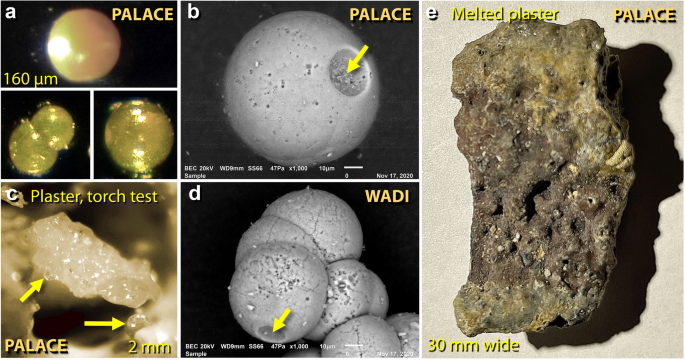
Images of calcium carbonate spherules and melted plaster from TeH. (a) Photomicrographs of translucent, amber-colored CaCO3 spherules from the destruction layer in the palace. (b) SEM image of 83-µm carbonate spherule with impact or outgassing crater at arrow. (c) Photomicrograph of ~ 2-mm-wide piece of partially melted palace plaster from oxygen/propylene torch test, showing incipient melting at 1500 °C. Arrows point to hemispheric droplets emerging as spherules. (d) 142-µm cluster of 8 carbonate spherules with apparent impact or outgassing crater at arrow. (e) 64 × 30 mm piece of melted plaster that broke off the palace wall and became melted. It is composed only of calcium, carbon, and oxygen.
Full size image
To explore a potential connection between plaster and spherules, we performed SEM–EDS on samples of the palace plaster. Comparison of SEM–EDS analyses shows that the plaster composition has a > 96% similarity to the spherule composition: CaCO3 = 71.4 wt.% in plaster versus 68.7 wt.% in the spherules; elemental C = 23.6 versus 26.3 wt.%; SiO2 = 2.4 versus 1.8 wt.%; MgO = 1.7 versus 2.0 wt.%; and SO3 = 0.94 versus 1.2 wt.%. The high carbon percentage and low sulfur content indicate that the plaster was made from calcium carbonate and not gypsum (CaSO4·2H2O). SEM imaging revealed that the plaster contains small plant parts, commonly used in plaster as a binder, and is likely the source of the high abundance of elemental C in the plaster. Inspection showed no evidence of microfossils, such as coccoliths, brachiopods, and foraminifera. The morphology of the spherules indicates that they are not authigenic or biological in origin.
Discussion of carbonate plaster and spherules
One of the earliest known uses of CaCO3-based plaster was in ~ 6750 BCE at Ayn Ghazal, ~ 35 km from TeH in modern-day Amman, Jordan97. At that site, multi-purpose lime plaster was used to make statues and figurines and to coat the interior walls of buildings. Because the production of lime-based plaster occurred at least 3000 years before TeH was destroyed, the inhabitants of TeH undoubtedly were familiar with the process. Typically, lime powder was produced in ancient times by stacking wood/combustibles interspersed with limestone rocks and then setting the stack on fire. Temperatures of ~ 800–1100 °C were required to transform the rocks into crumbly chalk, which was then mixed with water to make hydrated lime and plastered onto mudbrick walls97.
At TeH, fragments of CaCO3-based plaster are intermixed in covarying abundances with CaCO3-based spherules with both compositions matching to within 96%. This similarity suggests that the carbonate spherules are derived from the plaster. We infer that the high-temperature blast wave from the impact event stripped some plaster from the interior walls of the palace and melted some into spherules. However, it is difficult to directly melt CaCO3, which gives off CO2 at high temperatures and decomposes into lime powder. We investigated this cycle in a heating experiment with an oxygen/propylene torch and found that we could decompose the plaster at ~ 1500 °C, the upper limit of the heating test, and begin incipient melting of the plaster. The heated plaster produced emergent droplets at that temperature but did not transform into free spherules (Supporting Information, Text S2).
Similar spherules have been reported from Meteor Crater, where spherules up to ~ 200 μm in diameter are composed entirely of CaCO3 formed from a cosmic impact into limestone98,99. One of several possible hypotheses for TeH is that during the impact event, the limestone plaster converted to CaO with an equilibrium melting point of 2572 °C. However, it is highly likely that airborne contaminants, such as sodium and water vapor, reacted with the CaO and significantly lowered the melting point, allowing spherule formation at ≥ 1500 °C.
The proposed chemical sequence of events of plaster formation and the later impact are as follows:
- 1.
Limestone was heated to ~ 800–1100 °C, decomposing to quicklime:
$${\text{CaCO}}_{{3}} \to {\text{ CaO }} + {\text{ CO}}_{{2}}$$
- 2.
Quicklime was mixed with water to make a wet plaster:
$${\text{CaO }} + {\text{ H}}_{{2}} {\text{O }} \to {\text{ Ca}}\left( {{\text{OH}}} \right)_{{2}}$$
- 3.
The plaster hardened and slowly absorbed CO2 to revert to CaCO3:
$${\text{Ca}}\left( {{\text{OH}}} \right)_{{2}} + {\text{ CO}}_{{2}} \to {\text{ H}}_{{2}} {\text{O }} + {\text{ CaCO}}_{{3}}$$
- 4.
The high-temperature impact event melted some plaster into spherules:
$${\text{CaCO}}_{{3}} \to {\text{ CaO }}\left( {{\text{spherules}}} \right) \, + {\text{ CO}}_{{2}} \left( { > {15}00^\circ {\text{C}}} \right)$$
- 5.
CaO spherules slowly absorbed CO2 to revert to CaCO3:
$${\text{Ca }} + {\text{ CO}}_{{2}} \to {\text{ CaCO}}_{{3}} \left( {\text{as spherules}} \right)$$
General discussion of all spherules
According to the previous investigations17,72,81,82, Fe-rich spherules such as those found at TeH typically melt at > 1538 °C, the melting point of iron (Table 1). Because of the presence of magnetite (Fe3O4) in the REE spherule, its melting point is inferred to be > 1590 °C (Table 1). The Si-rich spherules are similar in composition to TeH sediment and mudbrick, and thus, we propose that they were derived from the melting of these materials at > 1250 °C. The carbonate-rich spherules likely formed at > 1500 °C.
Several studies describe a mechanism by which spherules could form during a low-altitude cosmic airburst100,101. When a bolide enters Earth's atmosphere, it is subjected to immense aerodynamic drag and ablation, causing most of the object to fragment into a high-temperature fireball, after which its remaining mass is converted into a high-temperature vapor jet that continues at hypervelocity down to the Earth's surface. Depending on the altitude of the bolide's disruption, this jet is capable of excavating unconsolidated surficial sediments, melting them, and ejecting the molten material into the air as Si- and Fe-rich spherules and meltglass. This melted material typically contains a very low percentage (< 1 wt.%) of impactor material102.
Melted zircon grains
To more accurately determine the maximum temperatures of the destruction layer, we used SEM–EDS to comprehensively investigate melted minerals on the outer surfaces of melted pottery and mudbricks. We searched for and analyzed zircon (melting point: ~ 1687 °C), chromite (~ 2190 °C), and quartz (~ 1713 °C)17.
Melted zircons in pottery and mudbricks were observed (Fig. 30) at an estimated density of 1 grain per 20 mm2. On highly melted surfaces, nearly all zircons showed some degree of melting. In contrast, nearly all zircons found on broken interior surfaces were unmelted (Fig. 30d), except those within ~ 1 mm of melted surfaces. This implies that the temperature of the surrounding atmosphere was higher than the internal temperatures of the melting objects. Unmelted potsherds displayed only unmelted minerals.
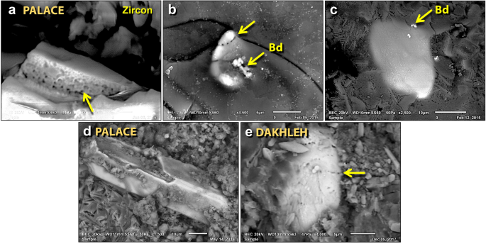
SEM images of melted zircon grains. (a) Melted TeH zircon grain with bubbles at yellow arrow due to high-temperature dissociation and/or entrapped porosity. (b) Melted TeH zircon grain decorated with bubbles along the fracture line at upper arrow; arrows labeled "Bd" point to bright granular baddeleyite, ZrO2, formed during the high-temperature dissociation of zircon. (c) Almost fully melted TeH zircon grain mixing into the Ca–Al–Si matrix. (d) A typical unmelted zircon grain from TeH with straight, euhedral edges. Grain shows cracks on the top surface from possible thermal or mechanical damage. (e) For comparison, from cosmic airburst/impact at Dakhleh Oasis in Egypt: melted zircon decorated with lines of bubbles (arrow).
Full size image
The melted zircons in TeH materials exhibit a wide range of morphologies. Most showed evidence of sufficient melting to alter or destroy the original distinctive, euhedral shape of the grains. Also, the grains were often decorated with vesicles that were associated with fractures (Fig. 30a, c).
Stoichiometric zircon contains 67.2 wt.% and 32.8 wt.% ZrO2 and SiO2 respectively, but in several TeH samples, we observed a reduction in the SiO2 concentration due to a loss of volatile SiO from the dissociation of SiO2. This alteration has been found to occur at 1676 °C, slightly below zircon's melting point of 1687 °C103. This zircon dissociation leads to varying ZrO2:SiO2 ratios and to the formation of distinctive granular textures of pure ZrO2, also known as baddeleyite104 (Figs. 30, 31, 32). With increasing time at temperature, zircon will eventually convert partially or completely to ZrO2. Nearly all zircons observed on the surfaces of melted materials were either melted or showed some conversion to baddeleyite. We observed one zircon grain (Fig. 32d–e) displaying granular ZrO2 associated with three phases that span a wide range of SiO2 concentrations, likely formed at temperatures above 1687 °C. This extreme temperature and competing loss of SiO over an inferred duration of only several seconds led to complex microstructures, where grains melted, outgassed, and diffused into the surrounding matrix.
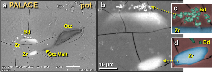
SEM images of other melted zircon grains in palace potsherd. (a) Two melted zircon grains adjacent to a previously discussed melted quartz grain; (b) close-up of same zircon grains; (c) manually constructed EDS-based phase map showing baddeleyite grains in green. The blue area represents melted zircon, while the red background represents the Ca–Al–Si matrix of the melted pottery. (d) Manually constructed EDS-based phase map of zircon grain showing small baddeleyite grains in green at the top.
Full size image
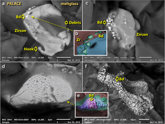
SEM images of melted zircon grains in mudbrick meltglass from the palace. (a) Thermally distorted zircon grain with a "hook" that resulted from the flow of molten material at > 1687 °C; the darker area represents unrelated debris on top of zircon. (b) Manually constructed EDS-based phase map showing baddeleyite grains (Bd = ZrO2) in green, zircon in blue, and melted mudbrick in red. (c) Zircon grain showing limited thermal alteration, yet sufficient to cause dissociation into bright baddeleyite grains at ~ 1676 °C. (d) Zircon grain exhibiting three phases of thermal alteration, as shown in detail in (e), where a manually constructed EDS-based phase map demonstrates that high temperatures caused bubbling in the center band of zircon (purple = Hi) producing sub-micron-sized grains of baddeleyite (e.g., at arrow). Medium temperatures caused zircon to melt and flow (blue = Lo), and lower temperatures at the left end of grain produced thermal cracks (medium blue = Med). The green area marks the high-Si diffusion zone resulting from the dissociation of zircon. (f) Zircon grain from TeH has been fully converted to granular baddeleyite.
Full size image
Discussion of melted zircon
Zircon grains have a theoretical, equilibrium melting point of ~ 1687 °C. Under laboratory heating17, zircon grains showed no detectable alteration in shape at ~ 1300 °C but displayed incipient melting of grain edges and dissociation to baddeleyite beginning at ~ 1400 °C with increasing dissociation to 1500 °C17. Most zircon grains < 50 µm completely melted at a temperature of ~ 1500 °C, while at ~ 1700 °C, the shapes of zircon grains > 120 µm were still recognizable but displayed considerable melting17. These experiments establish a lower melting range for TeH zircon grains of ~ 1400° to 1500 °C.
Patterson105 showed that zircon dissociation becomes favorable above 1538 °C and particles between 1 and 100 µm in size melted and dissociated when passing through a plasma, forming spherules with various amounts of SiO2 glass containing ZrO2 crystallites ranging in size from 5 nm to 1 µm. The majority of zircon crystals were monoclinic, but tetragonal ZrO2 was observed for the smaller crystallite sizes. Residence times were in the order of 100 ms, and the specific ZrO2 to SiO2 ratio within each spherule depended on the particle's time at temperature106.
Bohor et al.104 presented images of impact-shocked zircons from the K-Pg impact event at 66 Ma that are morphologically indistinguishable from those at TeH. Decorated zircon grains are uncommon in nature but commonly associated with cosmic impact events, as evidenced by two partially melted zircons from the known airburst/impact at Dakhleh Oasis, Egypt (Fig. 30e). The presence of bubbles indicates that temperatures reached at least 1676 °C, where the zircon began to dissociate and outgas. Similar dissociated zircon grains also have been found in tektite glass and distal fallback ejecta (deposited from hot vapor clouds). Granular baddeleyite-zircon has been found in the ~ 150-km-wide K-Pg impact crater107 and the 28-km-wide Mistatin Lake crater in Canada107. The dissociation of zircon requires high temperatures of ~ 1676 °C104, implying that TeH was exposed to similar extreme conditions.
Melted chromite grains
Examples of melted chromite, another mineral that melts at high temperatures, were also observed. Thermally-altered chromite grains were observed in melted pottery, melted mudbricks, and melted roofing clay from the palace. Their estimated density was 1 grain per 100 mm2, making them rarer than melted zircon grains. The morphologies of chromite grains range from thermally altered (Fig. 33a) to fully melted (Fig. 33b, d). One chromite grain from the palace displays unusual octahedral cleavage or shock-induced planar fractures (Fig. 33b). The typical chemical composition for chromite is 25.0 wt.% Fe, 28.6 wt.% O, and 46.5 wt.% Cr, although the Cr content can vary from low values to ~ 68 wt.%. SEM images reveal that, as chromite grains melted, some Cr-rich molten material migrated into and mixed with the host melt, causing an increase in Cr and Fe, and corresponding depletion of Si. The ratio of Cr to Fe in chromite affects its equilibrium melting point, which varies from ~ 1590 °C for a negligible amount of Cr up to ~ 2265 °C for ~ 46.5 wt.% Cr as in chromite or chromian magnetite ((Fe)Cr2O4), placing the melting point of TeH chromite at close to 2265 °C.
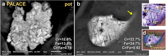
SEM images of melted chromite grains found on a melted potsherd from the palace. (a) Shattered, polycrystalline chromite grain that appears to have become agglutinated while molten. (b) Melted chromite grain, displaying cleavage (lamellae) suggestive of thermal and/or mechanical shock metamorphism at ~ 12 GPa; (c) close-up image showing angles between three sets of crystalline cleavage; (d) manually constructed EDS-based phase map showing chromite (purple) embedded in Ca–Al–Si matrix. The lines mark three sets of cleavage extending across the entire grain. A melt tail merging with the matrix is observed to trail off to the upper right of the grain at arrow.
Full size image
Discussion of melted chromite
Chromite grains theoretically melt at ~ 2190 °C. Moore et al.17 reported the results of heating experiments in which chromite grains in bulk sediment showed almost no thermal alteration up to ~ 1500 °C (Supporting Information, Fig. S8). At temperatures of ~ 1600 °C and ~ 1700 °C, the shapes of chromite grains were intact but exhibited limited melting of grain edges. These results establish a range of ~ 1600° to 1700 °C for melting chromite grains.
Because chromite typically does not exhibit cleavage, the grain exhibiting this feature is highly unusual. Its origin is unclear but there are several possibilities. The cleavage may have resulted from exsolution while cooling in the source magma. Alternately, the lamellae may have resulted from mechanical shock during a cosmic impact, under the same conditions that produced the shocked quartz, as reported by Chen et al.108 for meteorites shocked at pressures of ~ 12 GPa. Or they may have been formed by thermal shock, i.e., rapid thermal loading followed by rapid quenching. This latter suggestion is supported by the observation that the outside glass coating on the potsherd does not exhibit any quench crystals, implying that the cooling progressed very rapidly from liquid state to solid state (glass). This is rare in terrestrial events except for some varieties of obsidian, but common in melted material produced by atomic detonations (trinitite), lightning strikes (fulgurites), and cosmic airburst/impacts (meltglass)81. More investigations are needed to determine the origin of the potentially shocked chromite.
Nuggets of Ir, Pt, Ru, Ni, Ag, Au, Cr, and Cu in meltglass
Using SEM–EDS, we investigated abundances and potential origins (terrestrial versus extraterrestrial) of platinum-group elements (PGEs) embedded in TeH meltglass, in addition to Ni, Au, and Ag. Samples studied include melted pottery (n = 3); melted mudbrick (n = 6); melted roofing clay (n = 1), and melted lime-based building plaster (n = 1). On the surfaces of all four types of meltglass, we observed melted metal-rich nuggets and irregularly shaped metallic splatter, some with high concentrations of PGEs (ruthenium (Ru), rhodium (Rh), palladium (Pd), osmium (Os), iridium (Ir), and platinum (Pt)) and some nuggets enriched in silver (Ag), gold (Au), chromium (Cr), copper (Cu), and nickel (Ni) with no PGEs (Figs. 34, 35). Importantly, these metal-rich nuggets were observed only on the top surfaces of meltglass and not inside vesicles or on broken interior surfaces.
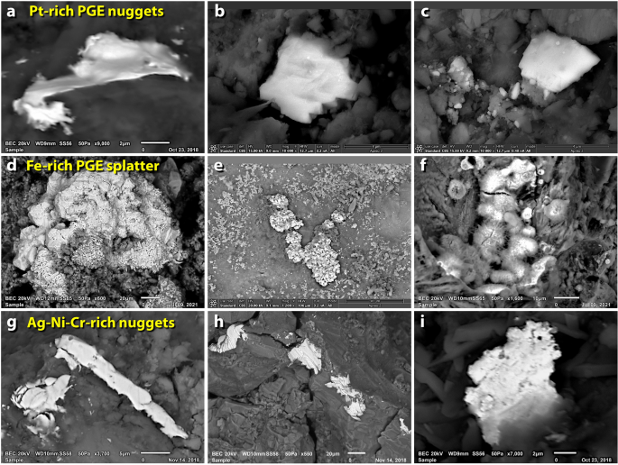
SEM images of nuggets of melted metals in mudbrick meltglass from the palace. (a)–(c) Pt-dominant TeH nuggets enriched in ruthenium (Ru), rhodium (Rh), palladium (Pd), osmium (Os), iridium (Ir), and platinum (Pt). (d)–(f) Fe-dominant TeH splatter is also enriched in PGEs. (g)–(i) Nuggets enriched in varying percentages and combinations of nickel (Ni), chromium (Cr), copper (Cu), and silver (Ag).
Full size image
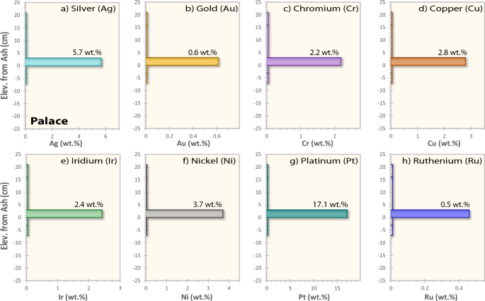
Average composition of selected metal-rich nuggets from the palace. (a-h) Silver (Ag), gold (Au), chromium (Cr), copper (Cu), iridium (Ir), nickel (Ni), platinum (Pt), and ruthenium (Ru), showing wt.% in selected nuggets from the destruction layer of the palace (7GG).
Full size image
Using SEM–EDS, we identified variable concentrations and assemblages of PGEs. The metallic particles appear to have melted at high temperatures based on the minimum melting points of the elements: iridium at 2466 °C; platinum = 1768 °C; and ruthenium = 2334 °C, indicating a temperature range of between approximately 1768° and 2466 °C. Our investigations also identified two PGE groups, one with nuggets in which Pt dominates Fe and the other with metallic splatter in which Fe dominates Pt.
Pt-dominant nuggets
We conducted 21 measurements on Pt-dominant TeH nuggets on meltglass (Fig. 34a–c). The nuggets average ~ 5 µm in length (range 1–12 µm) with an estimated concentration of 1 nugget per 10 mm2. For these nuggets, Fe concentrations average 1.0 wt.%, Ir = 6.0 wt.%, and Pt = 44.9 wt.% (Supporting Information, Tables S6, S7). The presence of PGEs was confirmed by two SEM–EDS instruments that verified the accurate identification of PGEs through analyses of several blanks that showed no PGE content. Some concentrations are low (< 1 wt.%) with high uncertainties (± 100 wt.%), and elemental concentrations greater than 10 wt.% have certainties of approximately ± 10 wt.%, making these results preliminary and indicating the need for further analyses. However, even though uncertainties are high, the relative elemental relationships of Fe > Pt or Pt > Fe were found to be consistent between the two instruments.
To determine the source of TeH nuggets and splatter, we constructed ternary diagrams. Terrestrial PGE nuggets are commonly found in ore bodies that when eroded, can become concentrated in riverine placer deposits, including those of the Jordan River floodplain. To compare Fe–Ir–Pt relationships among the TeH nuggets, we compiled data from nearby placer deposits in Greece109, Turkey110,111, and Iraq112, along with distant placers in Russia113,114,115, Canada116, and Alaska, USA117,118. The compilation of 109 Pt-dominant placer nuggets indicates that the average Fe concentration is 8.2 wt.%, Ir = 2.9 wt.%, and Pt = 80.3 wt.%. For the Ir-dominant placer nuggets (n = 104), Fe = 0.4 wt.%, Ir = 47.8 wt.%, and Pt = 5.3 wt.% (Supporting Information, Tables S6, S7). The ternary diagrams reveal that the values for Pt-dominant TeH nuggets overlap with Pt-dominant terrestrial placer nuggets but the Fe-dominant splatter is dissimilar (Fig. 36a).
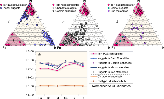
Ternary diagrams for PGE-rich grains. Comparison of Fe–Ir–Pt ratios of PGE-rich nuggets fused into the surfaces of TeH meltglass. There are two populations of TeH nuggets (red diamonds): Pt-dominant at #1 (top) and Fe-dominant at #2 (bottom left). (a) TeH Pt-dominant nugget group #1 (red diamonds) overlaps Pt-dominant but not Ir-dominant nuggets (blue circles) from placers and ophiolite deposits in Greece, Turkey, Iraq, Russia, Canada, and the USA. The Fe-dominant TeH nugget group #2 is geochemically dissimilar to all known placer nuggets, suggesting that these nuggets are not placer-derived. (b) TeH nuggets (red diamonds) compared to nuggets in carbonaceous chondrites (light gray circles) and nuggets in cosmic spherules (dark gray circles). Pt-dominant TeH nuggets in group #1 are a poor match, but Fe-dominant TeH splatter is an excellent match with chondritic meteorites and cosmic spherules, suggesting that they may be extraterrestrial in origin and that the impactor may have been a chondrite. (c) TeH nuggets (red diamonds) are a poor match for most nuggets in iron meteorites (purple circles), but an excellent match for nuggets found in comets (green circles). These data suggest that Fe-dominant PGE nuggets at TeH may have originated from cometary material. (d) Semi-log comparison of PGEs ruthenium (Ru), rhodium (Rh), palladium (Pd), osmium (Os), iridium (Ir), and platinum (Pt), normalized to CI chondrites. TeH Fe-dominant splatter (red line) is an excellent match for PGE nuggets in carbonaceous chondrites (blue line), cosmic spherules (purple line), micrometeorites (dark blue line), and iron meteorites (gray line). In contrast, TeH PGE nuggets are a poor match for bulk material from CI-normalized CV-type chondrites (e.g., Allende; orange line) and CM-type chondrites (e.g., Murchison; brown line).
Full size image
Fe-dominant splatter
We made 8 measurements on TeH Fe-dominant PGE splatter (Fig. 34d–f). The metal-rich areas average ~ 318 µm in length (range 20–825 µm) with an estimated concentration of 1 PGE-rich bleb per mm2, 100× more common than the TeH nuggets. Average concentrations are Fe = 17.5 wt.%, Ir = 4.7 wt.%, and Pt = 1.5 wt.%.
We explored a potential extraterrestrial origin by constructing ternary diagrams for comparison of TeH Fe-dominant splatter with known meteorites and comets (Fig. 36b, c). We compiled data for 164 nuggets extracted from carbonaceous chondritic meteorites (e.g., Allende, Murchison, Leoville, and Adelaide)119,120,121,122, seafloor cosmic spherules123,124, iron meteorites122,125, Comet Wild 2126, and cometary dust particles126. For average weight percentages, see Supporting Information, Tables S6, S7. The Fe-dominant TeH splatter (Fig. 36b) closely matches nuggets from carbonaceous chondrites and cosmic spherules but is a weak match for most iron meteorites (Fig. 36c). In addition, the TeH nuggets are similar to four cometary particles, two of which were collected during the Stardust flyby mission of Comet Wild 2 in 2004126. For average weight percentages, see Supporting Information, Tables S6, S7.
To further explore an extraterrestrial connection for TeH Fe-dominant splatter, we compiled wt.% data for TeH PGEs (Rh, Ru, Pd, Os, Ir, and Pt) and normalized them to CI chondrites using values from Anders and Grevasse127. We compared those values to CI-normalized nuggets in carbonaceous chondrites, including CV-type chondrites (e.g., Allende) and CM types (e.g., Murchison)119,120,122,128,129,130,131, seafloor cosmic spherules124, micrometeorites123, and iron meteorites122,125. These results are shown in Fig. 36d.
The TeH Fe-dominant splatter closely matches all types of extraterrestrial material with a similar pattern among all data sets: Pd has the lowest normalized values and Os and/or Ir have the highest, closely followed by Pt. The TeH splatter was also compared to the CI-normalized wt.% of bulk meteoritic material from CV- and CM-type chondrites (Fig. 36d). The composition of TeH splatter shows poor correlation with bulk chondritic materials, although the splatter is an excellent geochemical match with the PGE nuggets inside them. In summary, the CI normalization of PGEs suggests an extraterrestrial origin for the Fe-dominant TeH splatter, just as the ternary diagrams also suggest an extraterrestrial source. The correspondence of these two independent results suggests that the quantification of PGEs is sufficiently accurate in this study.
Another unusually abundant element, Mo, is also associated with Fe-dominant splatter but not with Pt-dominant nuggets. Mo averages 0.3 wt.% with up to 1.1 wt.% detected in Fe-dominant splatter but with none detected in TeH Pt-dominant nuggets. Mo also is not reported in any terrestrial placer nuggets and occurs in low concentrations (less than ~ 0.02 wt.%) in iron meteorites. In contrast, Mo is reported at high concentrations in PGE nuggets from carbonaceous chondrites (~ 11.5 wt.%), cosmic spherules (0.6 wt.%), and cometary material (5.8 wt.%). Thus, the Mo content of TeH splatter appears dissimilar to terrestrial material but overlaps values of known cosmic material, suggesting an extraterrestrial origin.
Based on the volume and weight of the meltglass, we estimate that the extraterrestrial-like metallic TeH Fe-dominant splatter represents < 1 wt.% of the total mass of meltglass. This low concentration is typical of low impactor content in impact ejecta (< 1 wt.%)102.
Ag, Au, Cr, Cu, and Ni in TeH nuggets
We also investigated nuggets that lack PGEs. The geochemistry of these nuggets shows two distinct populations, one Ni-dominant and one Fe-dominant (Fig. 34g–i). Twelve measurements of TeH samples show enrichments in Ag averaging 5.7 wt.%, Au = 0.6 wt.%, Cr = 2.2 wt.%, Cu = 2.8 wt.%, and Ni = 3.7 wt.%. All particles appear to have been melted at high temperatures: silver at ~ 961 °C; gold at 1064 °C; chromium at 1907 °C; copper at 1085 °C; and nickel at 1455 °C.
Ternary diagrams for Cr, Fe, and Ni show that some TeH nuggets exhibit chemical similarities to mineral deposits in Greece, Turkey, and Oman, suggesting that some nuggets are of terrestrial origin. However, other TeH nuggets are chemically similar to materials found in iron meteorites, chondrites, achondrites, and comets (Supporting Information, Fig. S9). When compared to meteoritic material, the Ni-dominant group roughly corresponds to measurements from sulfide inclusions in chondrites132, and the Fe-dominant group overlaps both chondritic sulfide inclusions and metal-rich grains from Comet Wild 2133. These results suggest that a small fraction (< 1 wt.% of bulk) of the Cr- and Ni-rich dust found embedded in TeH meltglass is of extraterrestrial origin, most likely ejected from an airburst/impact of either a meteorite or a comet.
Discussion of PGE nuggets
Importantly, the PGE-rich nuggets and splatter were observed embedded only on melted surfaces of the TeH meltglass but not inside the vesicles or within the meltglass. This suggests that the nuggets and splatter were not contained in the original sedimentary matrix but were fused onto the TeH glass while still molten. Geochemical analyses suggest a dual origin. The Pt-dominant nuggets do not match known extraterrestrial material and instead appear to be of terrestrial origin, possibly from placer deposits and regional mines. It is unclear exactly how they became embedded onto but not inside TeH meltglass, but one possibility is that they were originally buried as river-laid, PGE-rich placer deposits. If so, we propose that they were ejected during the impact event and distributed across the molten glass by the impact blast wave. Another possibility is that they derive from jewelry and raw precious metals in the palace complex that were pulverized and dispersed during the high-velocity destruction of the palace.
In contrast, the Fe-dominant nuggets fused into the surfaces of TeH meltglass closely match the composition of nuggets from chondritic meteorites, cosmic spherules, and comets, consistent with an extraterrestrial origin. The data suggest that a carbonaceous chondrite or a comet detonated in the air near TeH, pulverized PGE-rich nuggets within the bolide, accreted terrestrial placer nuggets, and dusted both terrestrial and extraterrestrial material across the surfaces of molten mudbricks, pottery, and building plaster at low concentrations of < 1 wt.%.
Platinum, iridium, and palladium in sediment
For TeH bulk sediment, neutron activation analyses show Pt abundance peaks in the destruction layer of all profiles tested (Fig. 37a–d) at ~ 2× to 8× an average crustal abundance of 0.5 ppb. Sedimentary Ir was below detection at < 0.1 ppb for the palace, temple, and ring road, but unusually high in the wadi, where values peaked at 1.0 ppb, ~ 50× larger than a crustal abundance of 0.02 ppb (Supporting Information, Table S3). Also, Pt/Pd ratios in bulk sediment from the destruction layers are anomalously higher than background layers by ~ 4× to 14× (Fig. 37e–h).
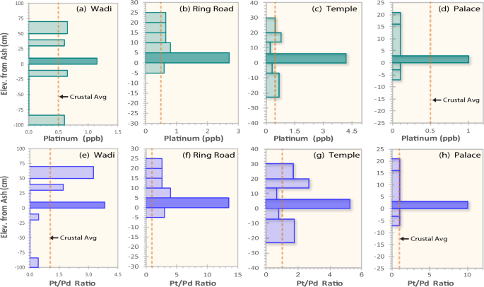
Plots for sedimentary Platinum and Palladium. (a)–(d) Platinum (Pt) concentrations. (e)–(h) Platinum/palladium ratios (Pt/Pd). Depths are in cm above or below the bottom of the destruction layer. Sample locations are labeled. Crustal abundance values (orange dashed lines) are ~ 0.5 ppb for Pt.
Full size image
Discussion of Pt, Ir, and Pd
Abundances of Pt, Ir, and the Pt/Pd ratios all peak in sediment at or near the top of the destruction layer, suggesting an influx of those elements at 1650 BCE, most likely from both extraterrestrial and terrestrial sources. Sedimentary concentrations of Ir only peak in the wadi samples and were not detectable at the other three sites for unknown reasons.
Meltglass vesicles lined with metal-rich minerals
The interior portions of many melted pieces of mudbrick, roofing clay, and pottery are highly vesicular, and the walls of these vesicles nearly always display an array of metal-rich crystals (Fig. 38). These include elemental iron and iron oxides, labeled as FeO, but is actually oxidized as hematite (Fe2O3) with a melting point of ~ 1565 °C; magnetite (Fe3O4) that melts at ~ 1590 °C; and/or elemental iron (Fe) melting at ~ 1538 °C (Fig. 38a, b, d, f, g). Also observed on vesicle walls were crystals of Fe phosphide (Fe2P) that melts at ~ 1100 °C (Fig. 38c, g), manganese oxide (MnO) at ~ 1945 °C (Fig. 38d), calcium phosphate (Ca3(PO4)2) at ~ 1670 °C (Fig. 38e), and calcium silicate (CaSiO2) at ~ 2130 °C (Fig. 38e).
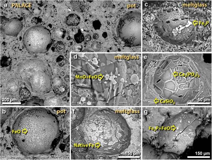
SEM images of gas vesicles in melted material from the palace. (a), (b) Vesicles in melted pottery are lined with crystals of iron and iron oxide (elemental Fe, Fe2O3, and/or Fe3O4). (c)–(g) Vesicles in melted mudbrick and roofing clay often are lined with a variety of crystals including elemental Fe, iron oxide, Fe phosphide (Fe2P), manganese oxide (MnO), calcium phosphate (Ca3(PO4)2), and calcium silicate (CaSiO3). These crystals are consistent with vapor deposition at high temperatures.
Full size image
Discussion of minerals in vesicles
In some cases, these mineral crystals appear to have crystallized from the molten matrix as it solidified. In other cases, it appears that they plated onto the vesicle surface, suggesting that they may have condensed through vapor deposition from the high-temperature, mineral-saturated atmosphere within the vesicle.
Melted iron and titanium
SEM inspection of the palace mudbrick meltglass revealed partially melted grains of magnetite (Fe3O4) with a melting point of ~ 1590 °C (Fig. 39a, b) and titanomagnetite (TiFe2O4) with a melting point of ~ 1550 °C (Fig. 39c, d). The latter is an oxyspinel that commonly occurs as discrete grains or as an exsolution product within magnetite. The chemical composition of magnetite at equilibrium is 72.36 wt.% Fe and 27.64 wt.% O. Titanomagnetite is 21.42 wt.% Ti, 49.96 wt.% Fe, and 28.63 wt.% O. SEM–EDS analysis confirms similar compositions for the observed TeH grains.
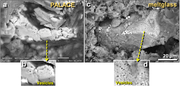
SEM images of melted iron and titanomagnetite in mudbrick meltglass from the palace. (a) Shattered elemental Fe grain containing < 0.1 wt.% oxygen as determined by SEM–EDS; (b) close-up showing surface porosity. (c) Titanomagnetite grain showing surface porosity; (d) close-up showing aligned porosity possibly along former grain boundaries. The cause of the porosity is uncertain, but because these grains are associated with other high-temperature melted minerals, we propose that this porosity resulted from exposure to high temperatures.
Full size image
Discussion of melted Fe and Ti
These grains display bubble-rich features that are commonly associated with grain fractures. There are several possibilities. (i) Approximately 20% of the time, magnetite grains are reported to be naturally overprinted by porous magnetite as a precipitation product, creating a bubble-like texture134. (ii) Alternatively, these features may be textures caused by differential dissolution135,136. (iii) The grains may have been exposed to temperatures equal to or greater than their melting point, causing the outgassing of volatiles or the rapid reduction of iron oxides. Because of the morphological dissimilarity of TeH grains to published examples of grains altered by precipitation and dissolution, we infer that these grains were altered by exposure to high temperatures.
Melted iron sulfide and iron phosphide
Sulfide and phosphide grains were found attached to the walls of the vesicles within mudbrick meltglass. SEM–EDS analyses of palace mudbrick meltglass identified melted Fe sulfide (FeS), also known as troilite (Figs. 40, 41), with a composition of 63.53 wt.% Fe and 36.47 wt.% S and a melting point of ~ 1194 °C. Commonly found associated with the Fe sulfide, Fe phosphide (Fe2P; Fig. 40b, e) is a nickel-poor variety of barringerite, a mineral first identified at Meteor Crater in Arizona. Another variant of Fe phosphide, Fe3P, was also identified in melted mudbrick from the palace. Both phosphide variants melt at ~ 1100 °C. Fe phosphide is common in meteorites, but although terrestrially rare, Fe2P is found in pyrometamorphic rocks, such as are found in the Hatrurim Formation in nearby Israel137. Britvin et al.137 report that the local Fe phosphide displays averages for Fe at 76.4 wt.% and P at 21.4 wt.%, with small amounts of Ni, Co, and Cr at 2.2 wt.%. The composition of Fe phosphide found at TeH is comparable, averaging 78.3 wt.% Fe and 21.7 wt.% P. However, unlike those Fe2P grains from Israel, the TeH grains lack detectable Ni, Co, and Cr.
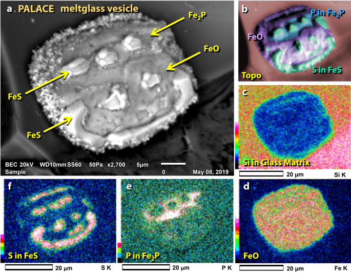
SEM images of Fe-S-P-enriched nugget in vesicle of mudbrick meltglass from the palace. (a) Chemically complex nugget inside a vesicle; contains Fe, S, and P. (b) Manually constructed EDS-based phase map showing that nugget is dominantly composed of Fe oxides, S as FeS, and P as Fe2P. (c)–(f) SEM–EDS elemental maps showing the composition of nugget by regions.
Full size image
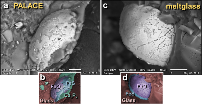
SEM images of Fe–S–Ca–P-rich grains in mudbrick meltglass from the palace. (a) Melted Fe-rich grain is chemically complex, containing Fe, S, Ca, and P. (b) Manually constructed EDS-based phase map marking areas of Fe oxides (purple, labeled as FeO), FeS (blue), and Ca3P2, calcium phosphide (green). (c) High-temperature melted Fe-rich grain; (d) manually constructed EDS-based phase map showing the area that is predominantly Fe oxide, bordered by a thin rim of FeS.
Full size image
Discussion of iron sulfide and phosphide
Visual inspection indicated that the sulfide and phosphide grains were attached to the inner surfaces of vesicles, and therefore, most likely formed by vapor deposition at > 1100 °C, rather than by crystallization from the melted matrix. Troilite (FeS) is very rare terrestrially but common in meteoritic material81,138. Harris et al.138 reported finding inclusions of troilite (FeS) as meteoritic clasts in Chilean meltglass proposed to have derived from a cosmic airburst that left meltglass on the surface along a 19-km-long stretch of the Atacama Desert approximately 12,800 years ago. At that site, troilite is typically found lining the walls of vesicles in the meltglass, as is the case for TeH meltglass.
Melted calcium phosphide
SEM–EDS analyses also show that vesicles in melted mudbrick from the palace contain calcium phosphide (Ca3P2) (Fig. 42). This mineral has a stoichiometric composition of ~ 66.0 wt.% Ca and ~ 34.0 wt.% P and melts at ~ 1600 °C (Table 1). Unlike Fe sulfide and Fe phosphide discussed above that appear to have formed by vapor deposition, these examples most likely crystallized from the molten Ca–Al–Si matrix material.
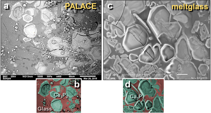
SEM images of calcium phosphide crystals in vesicles of mudbrick meltglass from the palace. (a) and (c) Crystals of calcium phosphide, Ca3P2, lining the inside wall of meltglass vesicles; (b) and (d) manually constructed EDS-based phase map of Ca3P2 (green) crystals embedded in typical Ca–Al–Si melted matrix.
Full size image
Melted calcium silicate (wollastonite)
SEM–EDS analyses of palace mudbrick meltglass (Fig. 43a, b) and melted pottery (Fig. 43c) reveal the presence of Ca silicate, also known as wollastonite (CaSiO3), with a composition of 48.3 wt.% CaO and 51.7 wt.% SiO2 and a melting point ~ 1540 °C (Table 1). These crystals are mostly found on broken surfaces of the matrix but also are sometimes observed inside vesicles. Unlike Fe sulfide and Fe phosphide above, which appear to have formed by vapor deposition, these crystals appear to have condensed from the molten matrix as it cooled.
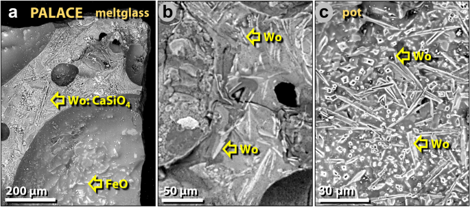
SEM images of wollastonite crystals in palace melted pottery and mudbricks. (a) Spindle-like crystals of wollastonite (CaSiO4) on the broken face of mudbrick meltglass. Crystals of iron oxide line the vesicle. (b) Wollastonite crystal within the meltglass matrix. (c) Wollastonite crystals within a vesicle of melted pottery.
Full size image
Human bones in the destruction layer
Upper tall
If the MB II destruction event at TeH was of sufficient magnitude and abruptness to be fatal for human inhabitants, as the evidence indicates, human remains should exist in the MB II layer. Indeed, human skeletal remains of sufficient size to be positively identified were found on the upper ring road that encircled the upper tall between the MB II defensive fortification wall and the outer wall of the MB II palace. Two human skulls were found about 20 cm apart (Fig. 44a, b), adjacent to a portion of a pelvis and a likely arm bone fragment. One skull was missing the mandible, and the right orbit was crushed about 50%. The second skull fragment consisted only of the upper dentition and lower half of the right orbit. Only two or three rib fragments were found and no other long bones were recovered. The forensic evidence suggests that the two bodies may have been decapitated, dismembered, and disarticulated. The record indicates that most of the bones had been shattered into small pieces and mixed into a matrix of pulverized mudbricks. Currently, it is not possible to determine if the small bones are from humans or small mammals, but their proximity to identifiable human bones makes it most likely that they are human. If so, only ~ 10% of the combined original bone mass of both humans is present as observable fragments within a 75-cm radius from the skulls. The remaining 90% of the two skeletons are missing and assumed to have been destroyed and/or located further away in the sediment matrix.
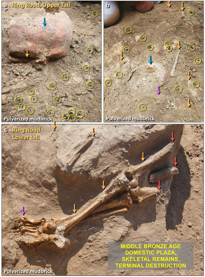
Human bones in the destruction layer. (a) Photo of a disarticulated skull found near the palace on the ring road around the upper tall. The right eye socket has been crushed (orange arrow). Skull is embedded in pulverized mudbrick containing numerous charcoal fragments (yellow circles) and is stained with ash commonly found in the destruction layer (blue arrow). The orange tint of the skull suggests it was exposed to temperatures > 200 °C141. (b) Rear view of the same skull in panel 'a' (blue arrow) near the second skull (purple arrow) and numerous disarticulated, fragmented human bones (orange arrows). Charcoal fragments at yellow circles. (c) Lower torso from the ring road of lower tall (orange arrows), and other disarticulated bones. Bones show evidence of being burned (red arrows); the rest of the skeleton is dismembered and disarticulated. Hyper-flexed toes (purple arrow) are consistent with either perimortem or postmortem exposure to high temperatures.
Full size image
These skeletons were found on the roadway around the upper tall, where the road was 3–4 m wide. The top of the nearby rampart was several meters wide. The remains were found at a depth of about four meters below the modern surface, well-sealed and undisturbed beneath archaeological sterile strata. The bodies had been rapidly entombed by pulverized mudbrick containing abundant ash and charcoal. No weapons were found associated with the skeletons or evidence of damage by weapons, and neither body showed any indication of exposure to scavengers. Although humans can be mortally affected by earthquakes, volcanism, and warfare, these bone characteristics, both individually and collectively, show no evidence that these human deaths were caused by such events. Furthermore, even though these bones were found in close association with large charcoal fragments, the bones lack evidence of direct exposure to fire, except for the extreme upper ends. Radiocarbon ages of the surrounding charcoal (~ 1650 BCE) are contemporary with those elsewhere in the destruction event.
We also searched and found human bone fragments in palace bulk sediments, ~ 15 m away from the skeletons on the ring road. We quantified bone abundance in the fraction using a > 1.2 mm screen (#12 ASTM sieve). The destruction layer was found to contain ~ 19 bone fragments per kilogram, weighing 3.2 g/kg. The largest bone was ~ 2.1 cm long × 0.8 cm wide (average size of bones = 0.6 × 0.2 cm). In nine other samples, three above the destruction layer and six below, no other bone fragments were observed. After excavating nearly 100 squares (0.36 ha or ~ 1% of the site), researchers have found ~ 10 partial human skeletons, out of an estimated city population of ~ 8000 people2. However, dozens to hundreds of broken and disarticulated bone fragments have been found in each of the 100 squares but these were too small to be conclusively identified as human or animal.
Lower tall
During Season 6139, excavations were conducted in two 6-by-6-m squares along the ring road of the lower tall. Both squares revealed a significant abundance of disarticulated and fragmented human skeletal remains in the MB II destruction layer139 (Fig. 44c). In one square, three partially intact skeletons were found. All bones observed were embedded in a loose debris matrix composed of pulverized mudbrick, ash, and charcoal (Fig. 44c). There are no indications of intentional burial, scavenging, accidental death, violence, or battle damage.
Two osteologists examined the bones of two adults and one child139. Disarticulation of the skeletons was generally severe, and for the adult skeletons, only leg bones were preserved. For one skeleton, ~ 10 cm of the ends of both femurs showed evidence of charring. The remaining skeleton was represented by many fragmented bones found in the surrounding matrix. Metatarsal bones were abnormally hyper-extended (i.e., joints were over-stretched) and the proximal phalanges were hyper-flexed at almost 90 degrees to the metatarsals. The right knee joint of one skeleton also was hyper-extended139. In a nearby child's skeleton, the legs were hyper-flexed backward and the knee joints were disarticulated. Another skeleton was found buried in a crouching position with the hands raised to the face, a posture commonly adopted for protecting the head, as occurred during the volcanic eruption at Pompeii140.
Bones were also found in another square, ~ 6 m south of the square containing the skeletons. This square contained ~ 100 bones/kg with average length of 5.0 mm (range 0.5 mm–4.7 cm) and average width of 1.0 mm (range 0.5–5.0 mm). The largest was a small rib bone (4 by 47 mm), either from a human infant or a small mammal. The bone fragments weighed ~ 6.0 g/kg.
We also observed a 3.5-mm-long charred bone that had been splashed with meltglass (Fig. 45). In one case molten sediment had partially melted and mixed with the bone, flowed, and cooled in place. Previous experiments by Moore et al.17 suggest that such melting occurs at ≥ 1500 °C.
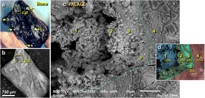
Bone fragment splattered with meltglass in the destruction layer. (a) Photomicrograph of 3.5-mm-long charred bone from the palace. The yellow boxed area indicates an area of melted glass on bone, as shown in panels 'c' and 'd'. Yellow arrows point to other areas with greenish meltglass fused to the bone. (b) SEM image of bone in panel 'a'. (c) SEM close-up image of boxed area in panel 'a'. Green dotted line marks the glass-to-bone boundary, as further shown in panel 'd'. #1 represents unmelted Ca–Al–Si-rich sediment with no bone component; #2–3 represent partially melted sediment mixed with melted bone (hydroxyapatite); #4 presents charred bone. (d) Colorized SEM image of panel 'c' showing gradation of bone-and-sediment mixing, based on multiple SEM–EDS analyses.
Full size image
These bones also were associated with geochemical anomalies. The rib bone is visibly salt-encrusted, measured by SEM–EDS at ~ 46 wt.% NaCl, and the NaCl content of the attached sediment was very high at ~ 54 wt.% (Fig. 46a). Anomalously high concentrations of salt were found only associated with the bones and sediment in the destruction layer at 1650 BCE, and not in strata above or below, indicating an unusual influx of salt at that time. The rib bone also exhibits several nuggets of silver and tin oxide (SnO2) (Fig. 46b) with morphologies suggesting that they splashed onto the bone and sediment while molten. Ag melts at ≥ 961 °C and SnO2 at ≥ 1630 °C, although elemental Sn melts at ~ 232 °C. The tin and silver nuggets are also similar to those observed in the surface of melted mudbricks in the palace that were found fused to meltglass in the temple complex (Fig. 46c) and observed splashed across loose sediment (Fig. 46d).
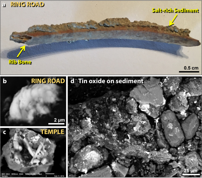
Bone associated with salt and melted tin oxide (SnO2). (a) Photomicrograph of 4.7-cm-long human or mammal rib bone from the ring road on the lower tall. NaCl is present at high concentrations in the sediment (~ 54 wt.%) and on the bone (~ 46 wt.%). (b) Tin oxide particle (SnO2) appears to have collided with sediment on the bone while it was molten, possibly as unoxidized tin. The melting point of SnO2 is ~ 1630 °C, but unoxidized tin melts at ~ 232 °C. (c) A similar tin oxide particle from the temple, ~ 150 m away from the lower ring road sampling site. Particles are fused into meltglass. (d) Tin oxide splashed onto sediment around the bone in panel 'a'.
Full size image
Discussion of human bones
A medical doctor (co-author T.W.) inspected the human bones and concluded that the injuries occurred perimortem, including damage to the eye socket of one skull. We propose that the individuals represented by the bones were violently torn apart by a powerful airburst/impact, leaving only a few hand and foot bones still articulated and unbroken. It would not be possible to duplicate these injuries and disperse the bones as found in this layer by warfare or by accidental falls from a great height, e.g., off the adjacent rampart. Although tornadoes (max winds of ~ 512 km/h or ~ 318 mph) can cause bone breakage, organ damage, and disarticulation (Supporting Information, Text S3), they are exceedingly rare in Jordan or Israel and typically of low intensity. In any event, no known tornado has been shown to burn bones and break them into small fragments.
The most severe known injuries to human bodies result from the impact of airborne high-velocity objects, such as during explosions and tornadoes (Supporting Information, Text S3). In addition, the ground-hugging blast wave from an airburst/impact would be laden with high-velocity missiles, including sand, gravel, pulverized mudbrick, plaster fragments, potsherds, broken branches, and shattered timbers. At tornado-force wind velocities and extremely high ambient temperatures, these missiles would be capable of incinerating/stripping flesh and crushing bones. Current evidence suggests that the human mortality rate at TeH was very high, so that most likely none of the ~ 8000 inhabitants survived.
Based on the distribution of human bones on the upper and lower tall, we propose that the force of a high-temperature, debris-laden, high-velocity blast wave from an airburst/impact (i) incinerated and flayed their exposed flesh, (ii) decapitated and dismembered some individuals, (iii) shattered many bones into mostly cm-sized fragments, (iv) scattered their bones across several meters, (v) buried the bones in the destruction layer, and (vi) charred or disintegrated any bones that were still exposed.
In summary, although man-made explosives and atomic bombs can account for an extreme range of damage to humans, they can be ruled out because of the age of the site. In addition, warfare, accidents, and tornadoes can be eliminated because they are incapable of causing the observed severe skeletal damage at TeH. The circumstances and condition of the human bones and fragments suggest that at the moment of death, these individuals were going about normal activities inside the palace, on the upper ring road, and/or on the rampart above the road, where they were struck by a high-temperature thermal pulse, followed by a hyper-velocity blast wave from a catastrophic cosmic airburst. This event was most likely larger than the airburst at Tunguska, Siberia in 1908, where ~ 500 reindeer and several herders within the blast radius suffered severe burns and were killed, but suffered no disarticulation142.
Implications of high salinity for agriculture
Early general observations at TeH indicated that the destruction layer is marked by anomalously high concentrations of salt. For example, where the carbon-rich, potentially fertile destruction layer is exposed on the surface of the lower tall, it is unsuitable for agriculture until the salts are leached using local spring water. Some areas of the lower tall have never been farmed, and the MB II surface exposed at ground level turns white with salt crystals following rainfall. For most excavated squares, the newly exposed MB II surface from each day's archeological excavation produced an obvious white salt crust overnight as humidity leached salt to the surface. Also, we observed that the newly exposed mud/ash mortar between mudbricks hardened after exposure because of salt crystals and that many pottery sherds and some bones from the destruction layer were encrusted with large salt crystals.
We also discovered melted salt crystals in the destruction layer. For example, some palace meltglass displayed blebs of non-crystalline, melted potassium chloride, KCl (Fig. 47), which has a melting point of ~ 772 °C and a boiling point of 1420 °C. KCl is stoichiometrically composed of ~ 52.4 wt.% K and 47.6 wt.% Cl. We also identified melted sodium chloride, NaCl (Fig. 47c, d), which has a melting point of 801 °C and a boiling point of 1465 °C. NaCl is composed of ~ 39.3 wt.% Na and ~ 60.7 wt.% Cl. Even though both of these salts melt at low temperatures and alone are not definitive indicators of a cosmic impact, they appear non-crystalline and are fused into the meltglass, making them indicative of exposure to temperatures sufficient to melt sediment (> 1200 °C). Also, the blebs display vesicles from outgassing, suggesting that they may have exceeded their melting points.
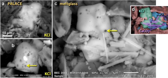
SEM images of melted potassium and sodium salt grains. (a), (b) Potassium chloride (KCl) grains melted into the surface of the palace mudbrick meltglass. (c) Melted NaCl and KCl grains. Bubbles at arrows suggest the salt grains exceeded their melting points. (d) Manually constructed EDS-based phase map of panel 'c', showing potassium chloride (KCl; green), sodium chloride (NaCl; blue), and spindle-like calcium carbonate crystals (CaCO3; purple).
Full size image
Using SEM–EDS analysis, six samples of melted mudbrick from the palace were found to average ~ 4.4 wt.% NaCl (range 2.0–9.1 wt.%), and one sample of pottery from the palace contains ~ 17.5 wt.% NaCl at its surface. For two samples from the temple, SEM–EDS analyses showed that some melted mudbrick contains an average of ~ 2.0 wt.% NaCl with associated sediment containing ~ 54 wt.% NaCl. Activation Laboratories in Canada used neutron activation analyses to determine salt content in samples from within, above, and below the MB II destruction layer from the palace and temple. The results showed a peak concentration of ~ 5.5 wt.% salt plus sulfate in the MB II layer, tapering off to about half or less above and below this layer. We also directly measured the salinity of these same samples, with the destruction layer containing ~ 4 wt.% salt in the palace and ~ 3.9 wt.% in the temple (Fig. 48). In both palace and temple areas, the salt content of two sediment samples above and two below the destruction layer exhibited values below detection at < 1 wt.%. The ring road displayed values of ~ 3 wt.% in the destruction layer (Fig. 48) but also had high values above and below, possibly due to the erosion of salt-rich sediment onto the road.
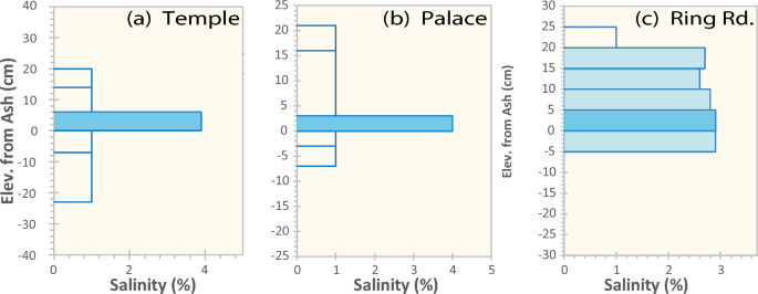
Salinity in TeH Sediment. Percentage of salinity for 3 sites, temple, palace, and ring road. The wadi site had < 1% salt content in all samples. Open bars mean below detection (< 1%).
Full size image
Discussion of causes for high salinity
Numerous lines of evidence reveal the sudden, catastrophic destruction of TeH at ~ 1650 BCE2. At the same time, archaeologists excavating nearby sites noted what they termed the "Late Bronze Age Gap"2,14,143, during which ~ 16 cities/towns, including TeH, and > 100 smaller villages144,145,146 were abandoned across the 30-km-wide lower Jordan Valley. This abandonment continued for the entire Late Bronze Age and most of the early Iron Age. Population levels are estimated to have plummeted from ~ 45,000–60,000 people to only a few hundred nomadic tribespeople inhabiting the area following this destruction event2. For TeH, the occupation gap is > 600 years2. In the Jericho area in the southwestern Jordan Valley, the archaeological record indicates a gap of approximately 300 years. For Tall Nimrin about 5 km north of TeH, there is a post-MBA occupation gap of ~ 500 years14,28,147, and in addition, excavators found remains of destroyed MB II walls. No walls were taller than ~ 2 m, or 10 courses of mudbricks14,28,147, and all were on the north side of Tall Nimrin, similar to 10-course-high TeH wall remnants that appear shielded from the proposed impact.
This multi-century abandonment is particularly puzzling, given that this area contains the most fertile agricultural land within a radius of hundreds of kilometers across Jordan, Israel, and Palestine. The destruction was so remarkable and so pervasive that the ensuing name of the area became Abel, the 'mourning grounds' (specifically, to mourn because of a calamity)148. This does not appear to have been some typical disaster that occasionally occurred due to warfare and earthquakes. Instead, it appears to have been a regional civilization-ending catastrophe that depopulated more than 500 km2 of the southern Jordan Valley for between 3 and 7 centuries2.
So, what could have caused the long-term abandonment of the entire lower Jordan Valley with its fertile agricultural land? One potential clue is that the destruction layers in both the palace on the upper tall and the temple on the lower tall contain salts at average concentrations of ~ 4%, ranging up to 54 wt.%, while conversely, salt concentrations above and below the destruction layers are undetectable at < 1 wt.%. In modern times, the surface sediments around TeH are non-saline at < 0.2% salt149 (Fig. 49). Elsewhere in the Kikkar, or southern Jordan Valley, ~ 26% of the area has salinity levels ≥ 1.3 wt.% with some parts > 5 wt.%149,150,151 (Fig. 49).
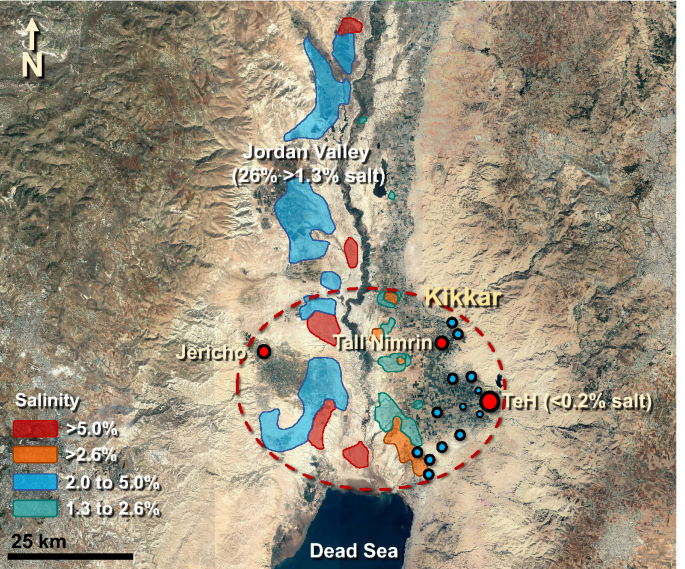
Salt and the 16 Cities of the Plain. Covering ~ 26% of the southern Jordan Valley, the colorized areas mark modern-day salinity concentrations of ≥ 1.3%, considered lethal for many domestic food crops. Tall el-Hammam (largest red dot) was the principal city in the area; Tall Nimrin was the next largest with smaller towns in blue. The dashed red oval indicates the extent of the Kikkar, known as the "disk of the Jordan". All 16 major settled sites and > 100 villages in the southern Jordan Valley appear to have been abandoned at ~ 1650 BCE (3600 cal BP). Jericho was minimally resettled ~ 300 years after the destruction event. Tall Nimrin was resettled ~ 500 years later, and TeH was reoccupied ~ 600 years later. Source of base image: "The Southern Jordan Valley". 35° 51.254 N, 35° 33.092 E. Google Earth; Maxar Technologies; CNES/Airbus. Imagery date: 10/29/2020; accessed: 4/4/2021. Permissions: https://about.google/brand-resource-center/products-and-services/geo-guidelines/ Modified by the authors using Adobe Photoshop CC2014 (adobe.com/products/photoshop.html).
Full size image
According to the US Department of Agriculture (USDA), wheat will not germinate if the soil salt content is > 1.3 wt.%, and barley will not germinate at > 1.8 wt.%152,153. Since these are the two primary cereal grains of the Ancient Near East, if the unusually high concentrations of salt recorded at TeH were similar throughout much of the southern Jordan Valley, no crops could have been grown until, with time, the salt leached out of the soil. Accomplishing the desalination of the soils would have taken hundreds of years, based on typical farming practices.
Although the precise origin of the peaks in salinity at TeH is unknown, we speculate that an impact into or an airburst above high-salinity surface sediments (26% of land in the southern Jordan Valley at > 1.3% salinity) and/or above the Dead Sea (with ~ 34 wt.% salt content) may have distributed hypersaline water across the lower Jordan Valley. If so, this influx of salt may have substantially increased the salinity of surface sediments within the city and in the surrounding fields. Any survivors of the blast would have been unable to grow crops and therefore likely to have been forced to abandon the area. After ~ 600 years, the high salt concentrations were sufficiently leached out of the salt-contaminated soil to allow the return of agriculture.
Coeval destruction and burning of Jericho
By ~ 1650 BCE, Tell es-Sultan, proposed as the biblical Jericho, reached its maximum extent154 at ~ 7 ha15, about one-fifth the size of TeH, located ~ 22 km to the east. Jericho was the most prosperous city in the area and the third largest after TeH and Tall Nimrin. For that time, it had state-of-the-art defenses with thick walls and a massive stone revetment155.
Then suddenly, the city suffered violent destruction and a fierce conflagration at the end of MB II at the same time as TeH26. Kenyon, an early site excavator, wrote "The destruction was complete. Walls and floors were blackened or reddened by fire, and every room was filled with fallen bricks, timbers, and household utensils; in most of the rooms the fallen debris was heavily burnt27".
During the destruction event, a massive stone MBA defensive tower toppled and burned26, leaving a thick layer of broken mudbricks, fire-cracked stones, broken pottery, and burned fragments of wooden beams26. Along the base of a massive curving stone defensive wall adjoining the tower, a 7-to-10-m-wide destruction layer contains a thick accumulation of ash, charcoal, and carbonized wooden beams, covered by huge stones, broken mudbricks, and rubble156. Marchetti et al.26, another key group of site excavators, noted that the ash was white, suggesting combustion at high temperatures. However, excavators reported finding no high-temperature materials, such as melted mudbricks or pottery, suggesting temperatures of less than ~ 1200 °C17, the melting point of local sediment.
Near the tower was a series of storerooms gutted by fire and filled with broken storage jars and carbonized grains that were strewn across the floors26,154,157. Almost no complete vessels were found, and instead, broken potsherds were suspended throughout the destruction matrix at different elevations26. In addition, human remains were found mixed within the debris layer, and almost all the bones were burned, disarticulated, and shattered into small fragments26. The excavators noted that their colors indicate exposure to high temperatures26.
Kenyon reported that the massive MBA eastern wall, which faced toward TeH, collapsed and some of the destruction debris cascaded down the steep slope adjoining the city walls158. She also concluded that the collapse of the eastward-facing fortifications had taken place before the walls were affected by fire27. Overlying the crumbled defensive walls, Kenyon uncovered a thick deposit of Iron Age material, but LBA material is missing24. Instead, up to one meter of culturally sterile sediment lies top the MBA destruction layer in places, leading Kenyon to conclude that for hundreds of years after the destruction of Jericho, the city lay abandoned155.
Discussion of the destruction of Jericho
The destruction of Jericho was not unusual. Cities in the Jordan Valley have a long history of episodic destructions by earthquakes and warfare154,158,159. However, Kenyon found no conclusive evidence of either at ~ 1650 BCE154, and there were no known major earthquakes in the area between ~ 1800 and 1560 BCE160. In previous destruction episodes, the inhabitants simply rebuilt immediately, but this time, Jericho was inexplicably abandoned for centuries155.
The causes of the destruction of Jericho are unclear. Notably, its age is 1653 ± 18 BCE (range 1670–1626 BCE), making it statistically coeval with the destruction of TeH at 1661 ± 20 BCE (range 1686–1632 BCE) (Fig. 50; Supporting Information, Tables S8, S9). One possibility is that Jericho's destruction resulted from the high-temperature thermal pulse and high-velocity blast wave of a cosmic airburst that first struck TeH and then Jericho, where it collapsed the fortified walls and burned the city, located ~ 22 km to the west of TeH. This is consistent with Tunguska, where Svetsov161,162 showed that the radiation energy from the Tunguska explosion was sufficient to set fires within a diameter of ∼20 km. Thus, for TeH, the minimum distance of destruction is ~ 22 km, similar to that of the Tunguska airburst in 190865,161,162,163.

Comparison of Dates of MBA Destruction of Jericho and TeH. Bayesian calculation showing essentially identical age ranges at 68% Confidence Interval for the destruction layers of the two cities. For TeH, the range is 1686–1632 BCE (1661 ± 21 BCE) and for Jericho 1670–1626 years BCE (1653 ± 18 BCE), for a common overlap of 38 years, making them statistically coeval.
Full size image
Potential causes of the city destruction
Here, we consider 10 processes that account for some or all of the wide-ranging observations and evidence related to the destruction of Tall el-Hammam and nearby cities/villages. Table 2 lists the potential matches for 17 lines of evidence for each of these possibilities. Using this evidence, we summarize which process best explains the observed evidence at TeH.
Anthropogenic activities
Matches 12 of 17 lines of evidence. These activities include glass-making; smelting gold, silver, and copper; and fashioning metals into jewelry and artifacts. During the MBA, copper smelting only reached temperatures of ~ 1100 °C164 and glass-making reached ~ 1100 °C164. These temperatures are too low to melt grains of chromite, quartz, or zircon at > 1500 °C, and pressures are far too low to shock quartz. Downward contamination of materials from modern human activities can be eliminated because most TeH meltglass is buried 2 m or more beneath archaeologically sterile layers.
Pottery-making
Matches only 1 of 17 lines of evidence. Maximum temperatures achievable during MBA pottery-making were < 1050 °C71, making this activity incapable of melting pottery and mudbrick at > 1400 °C. Also, this activity cannot melt zircon, quartz, and chromite grains at > 1500 °C and cannot produce peak concentrations in Pt, Ir, Ni, Cr, or shocked quartz.
Normal city fires/wildfires
Matches 8 of 17 lines. Besides the MB II destruction layer, several other non-MBA charcoal-rich strata were observed in the sedimentary record, indicating extensive TeH city fires at other times. However, none of those contain melted pottery, melted mudbricks, or any other high-temperature proxies. For comparison, after the Great Fire of London in 1666, several types of thermally-altered objects were found, including partially melted clay bricks, potsherds, and window glass165, but none show a degree of melting comparable to that at TeH. For a modern comparison, the firebombing of Dresden, Germany, during World War II produced updrafts of ~ 275 km/h, and yet, maximum temperatures were no higher than ~ 1000 °C166, which is high enough to soften but not melt glass, and too low to melt elemental iron at ~ 1538 °C. Typical non-impact fires cannot account for abundance peaks in Pt, Ir, Ni, and Cr, as well as the melting of zircon, quartz, and chromite, or shock metamorphism in quartz.
Midden fires
Matches 9 of 17. Biomass glass or slag is sometimes found in midden piles of prehistoric settlements in Africa with estimated formation temperatures of 1155–1290 °C71, and this process can produce vesicular meltglass and Si-rich spherules. However, Moore et al.17 investigated examples of this biomass glass and found that temperatures did not rise high enough to melt zircon, chromite, or quartz. Furthermore, midden fires cannot produce abundance peaks in Pt, Ir, Ni, and Cr or shock metamorphism in quartz.
Warfare
Matches 7 of 17. We considered whether ancient sieges could have led to city fires in the TeH destruction layer. However, only one arrowhead, and no spear points or swords were found associated with any of the skeletons found in the ruins. It is common in ancient warfare that conquered cities were demolished and replaced by the invading army's culture and religion, but there is no evidence for warfare in the destruction layer at TeH. In any event, ancient warfare is unable to explain melted high-temperature minerals, peaks in PGEs, and shocked quartz. For modern warfare, the detonation of military explosives can theoretically produce most of the evidence, but the TeH melted material comes from deeply buried strata sealed by Iron Age occupations unaffected by modern explosives. Modern defensive artillery revetments, excavated during the 1967 Middle Eastern war, were not coincident with the archaeological excavations that produced the evidence.
Earthquakes
Matches 5 of 17. Earthquakes can cause fires but are unable to explain most of the high-temperature melted materials, peaks in PGEs, and shocked quartz. Although earthquakes potentially can explain the directionality of the debris, all previous earthquakes left debris at TeH in the N/S orientation, aligned parallel to the Dead Sea rift, rather than in the observed SW/NE direction. In any event, no known major earthquakes occurred in the area in the interval from ~ 1800 to 1560 BCE160. The only two earthquakes known to have caused major damage at TeH occurred in ~ 2100 BCE (> 6.8 magnitude) and 3300 BCE (> 6.0 magnitude). After both of these disasters, the inhabitants of TeH simply rebuilt the city2.
Volcanism
Matches 12 of 17. Temperatures of most magmas are in the range of 700–1300 °C, but temperatures of komatiite magmas may occasionally reach 1600 °C167. These temperatures could account for the melted zircon but are too low to melt or mechanically shock grains of quartz168. Also, volcanism has never been shown to produce high-iron spherules, such as those found at TeH78,81,82.
One of the largest volcanic eruptions known for the last 10,000 years occurred at ~ 1663–1599 BCE (3613–3549 cal BP)169, centered in the eastern Mediterranean on Thera, a Greek island now known as Santorini. The explosion generated a massive tsunami that is proposed to have reached the island of Crete 110 km away and triggered the collapse of the Minoan culture, which evidence suggests was closely related to the culture at TeH143,170. Approximately 60 km3 of volcanic ash and pumice were ejected during this eruption171, and this debris buried the MBA town of Akrotiri on the island of Thera. Related tephra deposits have also been found in Turkey and Israel, and a thin (~ 1 mm) layer may have reached Jordan, including TeH171. However, this massive volcanic explosion was too distant from TeH (> 1000 km) to have caused its destruction, and also, it is dated at 40–100 years younger than the destruction and abandonment of TeH. We searched for but found no evidence at TeH of volcanic tephra, ash, pumice, or lava in any of the sedimentary profiles, indicating that no severe contemporary eruptions occurred near TeH at ~ 1650 BCE.
Lightning
Matches 13 of 17. Temperatures in lightning strikes can exceed 4000 °C, which is hot enough to boil zircon. Lightning strikes can also produce shocked quartz grains, but these shock lamellae are confined to the outer 0.33 µm of quartz grains and do not propagate into the interior, unlike the shocked grains found at TeH62. Furthermore, low values for remanent magnetism indicate that lightning could not have produced the TeH melted material tested. Also, lightning would not account for high-velocity winds, the directionality of debris, and the rapid destruction of buildings and walls spanning a distance of ~ 400 m across the tall.
Crater-forming cosmic impact
Matches 17 of 17. Although a hard impact potentially accounts for all of the evidence, this mechanism seems somewhat unlikely because there is currently no known crater in the area. However, although improbable, a crater with a diameter of less than a few hundred meters may be buried in the Jordan River floodplain or hidden underwater at the northern end of the Dead Sea. The Jordan Valley has been subject to massive seasonal floods for more than 3000 years, sufficient time for fluvial deposition to conceal a small crater. Alternately, an aerial burst of a bolide can produce a "shotgun blast" of small objects that can reach the ground and create small craters that range in diameter from a few meters to a few tens of meters. The action of wind and water could readily and rapidly erase any surface evidence of such craters especially in this area of rapid sediment deposition in the active floodplain of the lower Jordan Valley. Note in Table 3 that all the evidence for TeH matches that of crater-forming impacts such as the K–Pg, except for the lack of a crater.
Full size table
Cosmic airburst
Also matches 17 of 17 lines of evidence. Overall, one or multiple Tunguska-sized airbursts by a comet or meteorite seems most likely to account for the wide-ranging suite of observed evidence for the destruction of TeH (Table 3). In the future, it would be useful to search for proxies across the Jordan Valley at various distances from TeH. Any discernible pattern would help locate ground zero, where proxy concentrations would be the largest. We know from archeological evidence that 16 cities/towns and > 100 villages across the southern Jordan Valley were abandoned at this time, but not whether their walls were destroyed or if high-temperature, high-pressure proxies are present at those sites. Because airburst/impact proxies fall off exponentially with distance from ground zero, the distribution would help determine the intensity of the event.
It is worth speculating that a remarkable catastrophe, such as the destruction of Tall el-Hammam by a cosmic object, may have generated an oral tradition that, after being passed down through many generations, became the source of the written story of biblical Sodom in Genesis. The description in Genesis of the destruction of an urban center in the Dead Sea area is consistent with having been an eyewitness account of a cosmic airburst, e.g., (i) stones fell from the sky; (ii) fire came down from the sky; (iii) thick smoke rose from the fires; (iv) a major city was devastated; (v) city inhabitants were killed; and (vi) area crops were destroyed. If so, the destruction of Tall el-Hammam is possibly the second oldest known incident of impact-related destruction of a human settlement, after Abu Hureyra in Syria ~ 12,800 years ago17,172,173.
Analogous destruction events
Comparison to Trinity atomic detonation
In 1945, the first atomic bomb test, called Trinity, took place at the Alamogordo Bombing Range near Socorro, New Mexico. The bomb exploded in the atmosphere atop a 30-m tower, making the detonation an airburst in which the explosive yield equaled ~ 22 kilotons of TNT equivalent174,175. This atomic blast was several orders of magnitude less powerful than the Tunguska cosmic airburst in 1908 in Siberia, estimated at ~ 3–30 megatons of TNT equivalent at an altitude of 5–10 km176. The Trinity fireball had a maximum fireball temperature of ~ 300,000 °C175 and an average plume temperature of ~ 8000 °C64,177, hotter than the surface of the sun (> 5500 °C) and several times brighter81. After ~ 3 s, the plume temperatures fell to ~ 1713 °C175, the melting point of quartz.
The Trinity explosion formed a shallow crater ~ 1.4 m deep and ~ 80 m in diameter and ejected molten surface sediment that fell back as green glass, commonly referred to as trinitite. This melted green glass was found on the ground surface for a diameter of ~ 400 m, along with a high abundance of green glass spherules both macroscopic (0.1–5 mm) and microscopic (microns to tens of microns), the latter having been found as far as 2 km from ground zero. Bunch et al.81 reported the presence of high-temperature melted minerals in trinitite, indicating ground temperatures of > 2200 °C, consistent with reported conditions175.
Even though an atomic bomb blast is not applicable because of the historic absence of atomic explosions in the area, an atomic blast produces a wide range of melt products that are morphologically indistinguishable from the melted material found at TeH (Fig. 51). These include shocked quartz64; melted and decorated zircon grains (Fig. 51a, b); globules of melted material (Fig. 51c, d); meltglass containing large vesicles lined with Fe-rich crystals likely deposited by vapor deposition (Fig. 51e, f); spherules embedded in a meltglass matrix (Fig. 51g, h). Also, atomic detonations can replicate the physical destruction of buildings, the human lethality, and the incineration of a city, as occurred in World War II.
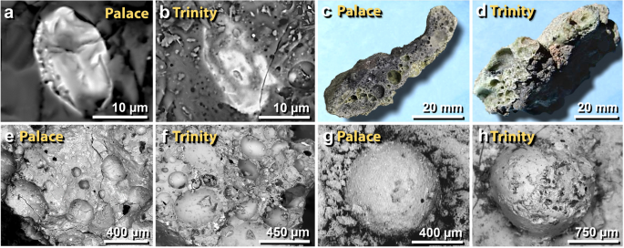
Comparison of melted materials from TeH with those from the Trinity atomic bomb test. (a), (b) SEM images compare a melted, decorated zircon embedded in mudbrick meltglass from the palace with similar material from Trinity. (c), (d) Photomicrographs compare a melted potsherd from the palace with similar-looking material from Trinity. (e), (f) The melted zircons in panels 'a' and 'b' were found in highly vesicular glass like these from the palace and the Trinity site, respectively. (g), (h) SEM images of a spherule fused onto mudbrick meltglass from the palace and a spherule embedded into trinitite from the Trinity atomic test.
Full size image
Comparison to Tunguska cosmic airburst
On June 30, 1908, a cosmic airburst occurred over Tunguska, Russia in a remote part of Siberia. The bolide has been variously estimated as a low-density rocky asteroid or a small comet with a diameter of 50–80 m65,162. The blast yield is estimated at ~ 3–30 megatons of TNT equivalent with a burst altitude of ~ 5–10 km. The airburst generated a pressure wave that toppled or snapped > 80 million trees, some up to 1-m in diameter178 across ~ 2000 km2 in a radial pattern away from ground zero65,162,179. The fallen trees partially burned across an area of ~ 200 km2 with a radius of ~ 8 km. Estimated wind velocities were ~ 40–70 m/s (144–250 km/h), greater than an EF-3 tornado180. Tunguska's blast pressure not only toppled trees but also pressed the tree fluids from the bark into the pre-existing tree rings of the surviving trees181. The Tunguska airburst deposited high-temperature melted spherules65,163, meltglass163,182,183, diamonds184,185, shocked quartz67,186, and iridium187. All these impact-related proxies have also been observed at TeH.
The temperature of the Tunguska fireball is unknown but estimated as > 10,000 °C188. The airburst initially ignited ~ 200 km2 of the forest before spreading to consume ~ 500 km2 of forest162. A similar but much smaller airburst occurred over Chelyabinsk, Russia, on February 15, 2013, with a yield of ~ 500 kilotons of TNT equivalent with a burst altitude of 12 km.
Even though the Tunguska area was sparsely inhabited, the blast killed ~ 3 of the ~ 30 people that were within or near the zone of fallen trees. Some of the injured survivors remained unconscious for hours to days142. Nearly everyone experienced severe burns within an eight-km radius of ground zero across an area covering ~ 200 km2. Also, as many as 500 reindeer were killed by the blast and hundreds more were severely burned142. Based on this evidence, we propose that an aerial detonation likely larger than the one at Tunguska destroyed TeH at ~ 1650 BCE.
To compare Tunguska to an airburst at TeH, we superimposed the ~ 2000 km2 area of 80 million trees fallen trees at Tunguska over the Dead Sea area at an exact comparative scale (Fig. 52). The Tunguska footprint would cover about one-third of the north end of the Dead Sea and most of the plain of the Jordan Valley, including TeH, Jericho, and other MB II cities. This map is shown for comparison only and is not intended to represent the proposed TeH impact event. Even so, it does indicate that if a relatively small Tunguska-scale cosmic event occurred over the Jordan Valley, the detonation and ensuing blast wave would have been energetic enough to have caused widespread destruction.
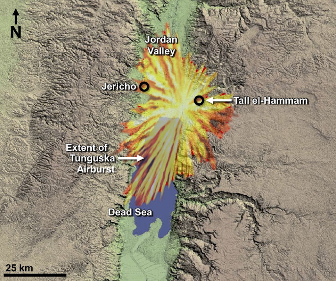
The extent of the cosmic airburst at Tunguska, Siberia (1908), superimposed on the Dead Sea area. The Tunguska blast was ~ 75 km wide N–S, affecting 2200 km2. This accurately scaled image shows that a cosmic airburst similar in energy to the one at Tunguska could cover a large segment of the Dead Sea and the Jordan Valley. Note that this overlay is for comparison only; the location, orientation, direction of travel, entry direction, and size of the proposed TeH impact is unknown. Source of base image: Shuttle Radar Topography Mission (SRTM) SRTMGL1 DEM of the Jordan Valley from February 2000 was obtained from https://earthexplorer.usgs.gov/ maintained by the USGS/Earth Resources Observation and Science (EROS) Center, Sioux Falls, South Dakota, accessed on 4/4/2021. Modified by the authors using Adobe Photoshop CC2014 (adobe.com/products/photoshop.html).
Full size image
Hypothetical Tunguska-class airburst near TeH
To estimate the airburst effects of a hypothetical impactor near TeH, we modeled a range of possible impactor diameters using the online Impact Calculator created by impact experts, Melosh et al.189,190. We present the results in Supporting Information, Tables S10–S11 as just two of many possible scenarios with large uncertainties189,190. We are not suggesting that these hypothetical models represent what occurred at TeH because there is insufficient evidence to do so. Nevertheless, the calculations demonstrate that 12- to 23-megaton Tunguska-like airbursts can theoretically account for all the evidence observed at TeH.
According to the Impact Calculator, a stony meteorite, descending at a 45° incidence angle would explode above a sedimentary surface ~ 5 km southwest of TeH. We consider two plausible impactor sizes of 60 m and 75 m in diameter, providing bounds for the impact scenarios. An object larger than approximately 80 m would likely excavate a significant crater nearly a km in diameter, and so, seems unlikely, since no craters are visible in the Jordan Valley. At the low end of the impactor size range, a 60-m object would detonate at an altitude of 4.7 km with a yield of ~ 12 MT, producing 917 km/h (570 mph) windspeeds 5 km away at TeH (Supporting Information, Table S10). At the high end of the range, a 75-m diameter object would detonate at an altitude of 1.3 km with a yield of ~ 23 MT, producing 1200-km/h (740 mph) windspeeds 5 km away at TeH, far greater than the largest Category-5 tornado ever recorded (~ 512 km/h = 318 mph) with a theoretical peak overpressure of ~ 2.5 bars (35 psi). Such wind speeds and pressures are greater than the tensile strength for adobe-style mudbricks of 0.12 MPa (17 psi) and flexural strengths of 0.17 MPa (25 psi)191,192,193,194, exceeding the pressure needed to demolish and pulverize mudbrick walls. Those pressures even exceed the destruction limits of modern buildings of reinforced concrete. Pressures of only ~ 0.14 MPa (20 psi) result in a > 99% human fatality rate. In addition, the Tunguska airburst produced a seismic shock of ~ 5.0 on the Richter scale178, and an impact-related earthquake of similar magnitude at TeH would have caused severe damage to the mudbrick walls of the city. For both size impactors, no single, large crater would form, but multiple large-to-small fragments would likely hit the surface, possibly forming small, shallow craters that may have been filled over time by wind and water.
At Jericho, ~ 15 km away from the center of the 75-m airburst, Category-3 hurricane wind velocities would have reached 216 km/h (134 mph) (Supporting Information, Table S11). For the 60-m impactor, windspeeds would have reached 237 km/h (147 mph), equivalent to an EF-3 tornado and powerful enough to shear and collapse mudbrick walls192. This is consistent with the estimated range of Tunguska wind velocities of ~ 40–70 m/s (144–250 km/h), a range equivalent to EF-3 through EF-5 tornadoes180.
Based on atomic testing and Tunguska, the fireball of both sizes of impactors is estimated to have expanded to ~ 1 km in diameter195 and reached temperatures exceeding 300,000 °C in the center175, many times higher than the surface of the sun (5500 °C). Both impactors would emit an intense thermal pulse (> 45 cal/cm2) that radiates at the speed of light, providing enough heat to melt silicate and other materials162,175. Temperatures would remain higher than the melting point of quartz (1713 °C) for > 25 s175, sufficient to produce meltglass. As the base surge (shock wave) propagates outward for a few seconds, it also provides sufficient heat to melt the surfaces of mudbricks, pottery, roofing clay, and plaster196,197.
The physical evidence from TeH suggests that ground temperatures briefly rose above 1850 °C, setting flammable materials on fire. These temperatures are far above ~ 150 °C that is considered lethal for humans, leading to a nearly 100% fatality rate of exposed humans194. In summary, the impact models that range from 12 to 23 megatons presented in Supporting Information, Tables S10, S11 are consistent with the observed evidence at TeH.
Comparison of TeH to the Tunguska airburst
The damage at TeH appears similar to but higher than that of the well-documented airburst at Tunguska, Siberia in 1908. A supercomputer-generated model of a hypothetical 15-megaton airburst at Tunguska was developed at Sandia National Laboratories by Boslough197 (Fig. 53). He wrote that when a bolide explodes in the atmosphere, a high-temperature jet of ionized gases and impactor fragments reaches Earth's surface at high velocity, excavates unconsolidated sediment, and expands radially outward in what is sometimes called a 'base surge'. Surface temperatures rise higher than the melting points of silica-rich materials, and the surge's radial velocity can exceed the speed of sound (1225 km/h or 761 mph). Radiative and convective heating can transform surface and excavated materials into meltglass101. Svetsov162 computer-modeled the airburst of an 80-m-wide impactor and found that radiative fluxes from the blast were sufficiently high to melt ~ 0.5 cm of surface sediment at > 1700 °C for a duration of ~ 20 s. This closely matches the half-centimeter-thick melting of mudbricks, pottery, and roofing clay observed TeH, making a hypothetical Tunguska-class airburst a plausible scenario. Even though the Sandia computer model has large uncertainties, the modeled scenario accounts for all the evidence, including the destruction of thick mudbrick walls at TeH and Jericho (Table 2).
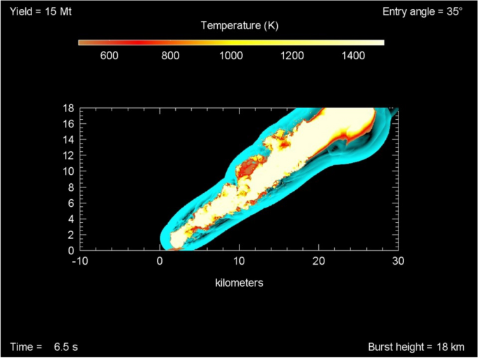
Supercomputer 15-megaton model of the Tunguska airburst. For the computer calculations of the airburst model, the entry angle is 35° and the detonation height is 18 km. After 6.5 s, the airburst width at the top is ~ 6 km. The hypervelocity jet of ionized gases and impactor fragments is ~ 2 km wide at the surface of the ground and expands at 1225 km/h (761 mph). The temperature scale at the top ranges from ~ 500° to 1500° K. Conference presentation slide 26 from Boslough197, Sandia National Laboratories (US Department of Energy) is in the public domain.
Full size image
Conclusions
An unusual 3600-year-old charcoal-rich destruction layer at Tall el-Hammam marks the sudden abandonment of a Middle-Bronze-Age urban center in the Jordan Valley close to the north end of the Dead Sea. Across the 30-km-wide lower Jordan Valley, 15 other cities and > 100 smaller villages were simultaneously abandoned at the end of the Middle Bronze Age to remain largely uninhabited for ~ 300–600 years. The remains of this ancient city and adjacent areas appear to be unique compared with those of other times, pointing to the occurrence of some highly unusual catastrophic event. The primary purpose of our research here has been to attempt to resolve this mystery.
An early crucial clue in this investigation was the discovery of highly vesicular potsherds in the debris matrix that appeared to have melted at high temperatures but with no clear evidence for a formation mechanism. This first discovery led to some general observations about the uniqueness of destruction layer debris, e.g., its unusual, high-temperature characteristics and its consistent SW-to-NE orientation. The site excavators speculated that the cause of the destruction may have been a cosmic airburst/impact, but they could not eliminate other potential mechanisms, including those related to warfare, volcanism, and tectonism.
These early observations stimulated our extensive investigation of the characteristics of the city's MB II destruction layer. We conducted many comprehensive, advanced, and quantitative investigations and analyses in attempting to distinguish among several potential formation mechanisms. Any plausible solution needed to be consistent with collectively explaining the extensive lines of evidence that suggested anomalously high-velocity winds, high temperatures, and high pressures associated with this destruction.
We investigated 14 major lines of evidence to investigate this unusual event: (i) shocked quartz grains that formed at pressures of ~ 5–10 GPa; (ii) vesicular pottery that melted at > 1500 °C; (iii) mudbricks and roofing clay that melted at > 1400 °C; (iv) high salt concentrations in sediment, including melted KCl and NaCl incorporated into melted mudbricks; (v) diamond-like carbon (diamonoids) that formed at high pressure and temperature; (vi) soot, charcoal and ash, indicating high-temperature fires; (vii) Fe- and Si-rich spherules, some of which melted at > 1590 °C; (viii) platinum, melted at ~ 1768 °C; (ix) iridium at ~ 2466 °C; (x) zircon at > 1687 °C; (xi) chromite at > 1590 °C; (xii) titanomagnetite at > 1550 °C; (xiii) quartz at 1713 °C; and (xiv) low remanent magnetism, a counter-indicator of lightning strikes.
We considered and dismissed 8 of 10 potential processes (Table 3), including volcanism, warfare, and tectonism, that can account for at least some but not all of the evidence. We conclude that the only plausible formation mechanism that can account for the entire range of evidence in Table 3 is a crater-forming impact or a cosmic airburst, most likely somewhat larger than the 22-megaton airburst at Tunguska, Siberia in 1908. The data also suggest an airburst occurred a few kilometers SW of Tall el-Hammam causing, in rapid succession, a high-temperature thermal pulse from the fireball that melted exposed materials, including roofing clay, mudbricks, and pottery. This was followed by a high-temperature, hypervelocity blast wave that demolished and pulverized mudbrick walls across the city, leveling the city, and causing extensive human mortality. An important observation is that although local sediment can melt at ~ 1300 °C, that is a minimum temperature but not a maximum one, a conclusion that is supported by the presence of embedded minerals that melted at temperatures of up to ~ 2500 °C. In addition, anomalously high salt content in the debris matrix is consistent with an aerial detonation above high-salinity sediments near the Jordan River or above the hypersaline Dead Sea. This event, in turn, distributed salt across the region, severely limiting regional agricultural development for up to ~ 600 years.
Regarding this proposed airburst, an eyewitness description of this 3600-year-old catastrophic event may have been passed down as an oral tradition that eventually became the written biblical account about the destruction of Sodom. There are no known ancient writings or books of the Bible, other than Genesis, that describe what could be construed as the destruction of a city by an airburst/impact event. This airburst/impact hypothesis would make Tall el-Hammam the second oldest known city/town to have been destroyed by an airburst/impact event that produced extensive human casualties, after Abu Hureyra, Syria at ~ 12,800 cal BP17. Similarly small but devastating cosmic events are expected to recur every few thousand years189, and although the risk is low, the potential damage is exceedingly high, putting Earth's cities at risk and encouraging mitigation strategies.
Methods
Optical and electron microscopy
Samples were processed and analyzed using previously published protocol72,75,76,81. After size-sorting with multiple screens (American Society for Testing and Materials) ranging from 4.75 mm to 53 µm, spherules and meltglass were examined using optical microscopy and electron microscopy. SEM–EDS analyses were conducted in low-vacuum mode using a JEOL-6000 SEM system and a ThermoFisher Apreo 2. Using SEM–EDS, we manually selected for detection of Fe, Ni, Mo, Ru, Rh, Pd, Os, Ir, and Pt, if present, with uncertainties of approximately ± 100% for concentrations < 1.0 wt.% and ± 10% for larger concentrations. Measurements and analyses were performed by T.D.B., Gary Chandler, M.A.L, A.V.A., T.E.B., J.H.W., C.M., D.B., K.L., and A.W.
Shocked quartz analyses
(i) Sediment was treated with HCl to remove carbonates. (ii) Sedimentary grains were wet-sieved and sorted to ≥ 150 µm and ≤ 850 µm. (iii) Mixed grains were embedded in blue-tinted epoxy on 26 × 47x1 mm slides for better visibility; thin-sectioned to ~ 30 µm; and highly polished for microprobe analyses at Spectrum Petrographics http://www.petrography.com/ No cover slide was used. (iv) Next, the slides were etched by immersion for ~ 1–2 min in a 30% solution of hydrofluoric acid (HF) liquid or alternately, exposed to HF vapor for ~ 1.5 min to dissolve amorphous quartz and make any lamellae more visible. The vapor produced more consistent results. (v) After treatment with liquid HF, we performed a dH2O rinse; neutralized with 5% sodium carbonate solution; rinse with dH2O again; then treated with 5% HCl to removed carbonates. After treatment with HF vapor, we performed a dH2O rinse. (vi) Candidate grains were identified on the polished slides using optical microscopy (transmitted light, reflected light, and epi-illumination under both plane and crossed polarization). (vii) The compositions of candidate grains were then investigated using SEM–EDS and (viii) using a cathodoluminescence detector (CL). Analyses were performed on uncoated thin sections in low-vacuum mode on a ThermoFisher Apreo 2 SEM. CL Images were acquired at ~ 10 mm working distance using 10 kV and 3.2 nA of beam current, with 50 Pa of chamber pressure to balance charge. Individual images using red, blue, and green wavelength filters on the CL detector were acquired and composited to form the final CL images. (ix) Then, the relative angles of lamellae on candidate grains were measured using a Leitz universal stage mounted onto a Leitz polarizing microscope. The accuracy of U‐stage measurements is estimated at ± 5°. (x) Finally, the relative angles of lamellae to the c axis were compared to known crystallographic axes of quartz and plotted using a computer program, A.N.I.E, Automated Numerical Index Executor55. Analyses were performed by K.L., A.W., M.A.L., A.V.A., and T.E.B.
Electron microprobe analyses
Standard practices were followed for all samples investigated by electron microprobe. Selected samples of melted pottery were embedded in epoxy, mounted to 25 × 51 × 1 mm slides, and polished to a microprobe finish at a thickness of ~ 30 µm. Analyses were performed by Nelia Dunbar and T.D.B.
Neutron activation analysis
Sediment samples were analyzed by ActLabs, Canada, using INAA to measure elemental abundances. For 56 elements, including Pt, Pd, Au, along with LOI, and salinity, bulk sediment samples of ~ 50 g each and magnetic fractions of ~ 1 g were analyzed using INAA, fire assay, and/or inductively coupled plasma mass spectrometry (ICP-MS) with a lower detection limit of 0.1 parts per billion (ppb). The accuracy of the laboratory results was verified with blanks and known standards.
Heating experiments
For the furnace experiments, a 26-mg powdered sample of unmelted TeH pottery was heated at 10 °C/min under argon purge using simultaneous Differential Scanning Calorimetry with Thermogravimetric Analysis (DSC-TGA). The cooled sample was investigated for signs of melting using optical microscopy. Experiments were performed by Allison Sikes, Bhavesh Patel, and M.P.
Remanent magnetism
Two pottery samples from TeH were weighed and affixed to a holder designed to measure the variation of the magnetization vector through stepwise laboratory-induced demagnetization in three perpendicular axes. The remanent magnetism instrument measures weak magnetic fields enabled by a superconducting quantum interference device containing Josephson junctions made by 2G Enterprises. The noise level of this instrument was 1e−8 A/m of the measured magnetic moment. The magnetic acquisition was acquired with pulse magnetizer ASC Model IM-10-30. G.K. performed the analyses.
Diamonoids and diamond-like carbon
A standard protocol used to isolate nanodiamonds and other acid-resistant species of carbon has been developed and used successfully at several dozen sites31. For this study, there was one modification: diamond-containing residues were treated with sulfuric acid following their extraction to dissolve gypsum (CaSO4·2H2O) to release potentially encapsulated diamonds. Details can be found in Supporting Information, Methods S1 and Fig. S10. Images were acquired using transmission electron microscopy (TEM). Extractions were conducted by W.S.W. and J.K.
Soot analyses
Soot carbon was extracted from sediment samples following a chemothermal oxidation procedure (CTO-375)198. Samples were demineralized, sequentially at 0.2, 2, and 6 N HCl until effervescence ceased, and then dried. Dried samples were manually ground in a mortar and pestle to fine dust, and then thermally oxidized in a muffle furnace. The furnace was set to a 24-h cycle, with 6 h to ramp the temperature up to 375 °C, where it was held for twelve hours, followed by a six-hour cool-down period. The isolated residue is operationally defined as soot. Soot samples were ground using a mortar and pestle, and then gravimetrically placed in small tin capsules which were sent to the UC Davis Stable Isotope Facility for quantification of carbon abundance and its stable isotopic signature. Experiments were conducted by S.M. and A. M-B.
Aciniform carbon (AC)
A standard protocol was used to extract AC/soot from bulk sediment31,179,199,200,201,202. The process consists of multiple steps: (1) demineralization through multiple treatments of hydrofluoric acid (HF) and hydrochloric acid (HCl); (2) oxidation to separate organic material from elemental carbon using acidic potassium dichromate; (3) SEM analysis to differentiate between AC/soot and non-soot carbon; and (4) examination of micrographs to quantify soot vs non-soot carbon abundances using particle size analysis. Experiments were conducted by W.S.W. and J.K.
Data availability
All supporting data are included in this manuscript. Sediment is available from Phillip Silvia at pjsilvia49@msn.com.
References
- 1.
Collins, S., Kobs, C. M. & Luddeni, M. C. The Tall al-Hammam Excavations, Volume 1: An Introduction to Tall al-Hammam: Seven Seasons (2005–2011) of Ceramics and Eight Seasons (2005–2012) of Artifacts from Tall al-Hammam. (Penn State Press, 2015).
- 2.
Silvia, P. J. The Middle Bronze Age civilization-ending destruction of the Middle Ghor. Ph.D. thesis, Trinity Southwest University (2015).
- 3.
Collins, S., Byers, G. A. & Kobs, C. M. The Tall al-Hammam Excavation Project, Season Fourteen 2019 Report: Excavation, Interpretations, and Insights (Department of Antiquities of Jordan, Amman, Jordan, 2019).
- 4.
Collins, S., Byers, G. A. & Kobs, C. M. The Tall al-Ḥammām Excavation Project, Season Ten 2015 Report: Excavation, Interpretations, and Insights (Department of Antiquities of Jordan, Amman, Jordan, 2015).
- 5.
Collins, S., Byers, G. A. & Kobs, C. M. The Tall al-Ḥammām Excavation Project, Season Eleven 2016 Report: Excavation, Interpretations, and Insights (Department of Antiquities of Jordan, Amman, Jordan, 2016).
- 6.
Collins, S., Byers, G. A. & Kobs, C. M. The Tall al-Ḥammām Excavation Project, Season Twelve 2017 Report: Excavation, Interpretations, and Insights (Department of Antiquities of Jordan, Amman, Jordan, 2017).
- 7.
Collins, S., Byers, G. A. & Kobs, C. M. The Tall al-Ḥammām Excavation Project, Season Thirteen 2018 Report: Excavation, Interpretations, and Insights (Department of Antiquities of Jordan, Amman, Jordan, 2018).
- 8.
Galli, P. Active tectonics along the Wadi Araba-Jordan Valley transform fault. J. Geophys. Res. Solid Earth 104, 2777–2796. https://doi.org/10.1029/1998JB900013 (1999).
Article Google Scholar
- 9.
Abed, A. M. An overview of the geology and evolution of Wadi Mujib. J. Nat. Hist. 4, 6–28 (2017).
Google Scholar
- 10.
Neev, D. & Emery, K. O. The Destruction of Sodom, Gomorrah, and Jericho: Geological, climatological, and archaeological background. 192 (Oxford University Press, 1995).
- 11.
Frumkin, A. & Elitzur, Y. Historic Dead Sea level fluctuations calibrated with geological and archaeological evidence. Quatern. Res. 57, 334–342 (2002).
ADS Article Google Scholar
- 12.
Kagan, E. J., Langgut, D., Boaretto, E., Neumann, F. H. & Stein, M. Dead Sea levels during the Bronze and Iron ages. Radiocarbon 57, 237–252 (2015).
Article Google Scholar
- 13.
Hennessy, J. B. Preliminary report on a first season of excavations at Teleilat Ghassul. Levant 1, 1–24 (1969).
Article Google Scholar
- 14.
Flanagan, J. W. & McCreery, D. W. First Preliminary Report of the 1989 Tell Nimrin Project. Annu. Dept. Antiquit. Jordan 34, 131–152 (1990).
- 15.
Marchetti, N., Nigro, L. & Sarie, I. Preliminary report on the first season of excavations of the Italian–Palestinian expedition at Tell es-Sultan/Jericho, April–May 1997. Palest. Explor. Q. 130, 121–144 (1998).
Article Google Scholar
- 16.
Collins, S. et al. Tall al-Ḥammām: Preliminary report on four seasons of excavation (2006–2009). ADAJ 53, 385–414 (2009).
Google Scholar
- 17.
Moore, A. M. T. et al. Evidence of cosmic impact at Abu Hureyra, Syria at the younger Dryas Onset (~12.8 ka): High-temperature melting at > 2200 °C. Sci. Rep. 4185 (2020).
- 18.
Ramsey, B. C. Bayesian analysis of radiocarbon dates. Radiocarbon 51, 337–360 (2009).
CAS Article Google Scholar
- 19.
Ramsey, B. C. Probability and dating. Radiocarbon 40, 461–474 (1997).
Article Google Scholar
- 20.
Reimer, P. J. et al. The IntCal20 northern hemisphere radiocarbon age calibration curve (0–55 cal kBP). Radiocarbon 62, 725–757. https://doi.org/10.1017/RDC.2020.41 (2020).
CAS Article Google Scholar
- 21.
Telford, R. J., Heegaard, E. & Birks, H. J. B. All age–depth models are wrong: but how badly?. Quatern. Sci. Rev. 23, 1–5 (2004).
ADS Article Google Scholar
- 22.
Kennett, J. P. et al. Bayesian chronological analyses consistent with synchronous age of 12,835–12,735 Cal B.P. for Younger Dryas boundary on four continents. Proc. Natl. Acad. Sci. 112, E4344–4353 (2015).
- 23.
Schiffer, M. B. Radiocarbon dating and the "old wood" problem: the case of the Hohokam chronology. J. Archaeol. Sci. 13, 13–30 (1986).
Article Google Scholar
- 24.
Kenyon, K. M. Excavations at Jericho, 1952. Palest. Explor. Q. 84, 62–82 (1952).
Article Google Scholar
- 25.
Nigro, L. The Italian-Palestinian expedition to tell es-Sultan, Ancient Jericho (1997–2015): Archaeology and valorisation of material and immaterial heritage 175–214 (Archaeopress, 2020).
Book Google Scholar
- 26.
Marchetti, N. A century of excavations on the Spring Hill at Tell es-Sultan, ancient Jericho: A reconstruction of its stratigraphy. (University of Rome; Palestinian Dept. of Antiquities, 2000).
- 27.
Kenyon, K. M. Excavations at Jericho/Vol. 3, The architecture and stratigraphy of the Tell Plates. (Brit. School of Archeology in Jerusalem, 1981).
- 28.
Flanagan, J. W., McCreery, D. W., Yāsīn, H. A. N. & Kehrberg, I. Tall Nimrin: Preliminary report on the 1995 excavation and geological survey. Annu. Dept. Antiquit. Jordan 40, 271–292 (1996).
- 29.
Carlisle, D. B. & Braman, D. R. Nanometre-size diamonds in the Cretaceous/Tertiary boundary clay of Alberta. Nature 352, 708–709 (1991).
ADS CAS Article Google Scholar
- 30.
Hough, R. M., Gilmour, I. & Pillinger, C. T. Carbon isotope study of impact diamonds in Chicxulub ejecta at Cretaceous-Tertiary boundary sites in Mexico and the Western Interior of the United States in Large Meteorite Impacts and Planetary Evolution II, Special Paper Vol. 339 (eds B.O. Dressler & V.L. Sharpton) 215–222 (1999).
- 31.
Kinzie, C. R. et al. Nanodiamond-rich layer across three continents consistent with major cosmic impact at 12,800 cal BP. J Geol 122, 475–506 (2014).
ADS CAS Article Google Scholar
- 32.
Schoell, M. & Carlson, R. M. Diamondoids and oil are not forever. Nature 399, 15–16 (1999).
ADS CAS Article Google Scholar
- 33.
Bruce, L. F., Kopylova, M. G., Longo, M., Ryder, J. & Dobrzhinetskaya, L. F. Luminescence of diamonds from metamorphic rocks. Am. Miner. 96, 14–22 (2011).
ADS CAS Article Google Scholar
- 34.
De Araujo, P. L. B., Mansoori, G. A. & De Araujo, E. S. Diamondoids: Occurrence in fossil fuels, applications in petroleum exploration and fouling in petroleum production. A review paper. Int. J. Oil Gas Coal Technol. 5, 316–367 (2012).
- 35.
Omotoyinbo, J. A. & Oluwole, O. Working properties of some selected refractory clay deposits in South Western Nigeria. (2008).
- 36.
Haccuria, E., Crivits, T., Hayes, P. C. & Jak, E. Selected phase equilibria studies in the Al2O3–CaO–SiO2 system. J. Am. Ceram. Soc. 99, 691–704 (2016).
CAS Article Google Scholar
- 37.
Kletetschka, G. & Wieczorek, M. A. Fundamental relations of mineral specific magnetic carriers for paleointensity determination. Phys. Earth Planet Inter. 272, 44–49 (2017).
ADS CAS Article Google Scholar
- 38.
Klokočník, J. et al. Support for two subglacial impact craters in northwest Greenland from Earth gravity model EIGEN 6C4 and other data. Tectonophysics, 228396 (2020).
- 39.
Kletetschka, G., Kohout, T. & Wasilewski, P. J. Magnetic remanence in the Murchison meteorite. Meteorit. Planet Sci. 38, 399–405 (2003).
ADS CAS Article Google Scholar
- 40.
Kletetschka, G., Uria, A. O., Zila, V. & Elbra, T. Electric discharge evidence found in a new class of material in the Chicxulub ejecta. Sci. Rep. 10, 1–11 (2020).
Article CAS Google Scholar
- 41.
Kletetschka, G. et al. Cosmic-impact event in lake sediments from Central Europe postdates the Laacher See eruption and marks onset of the Younger Dryas. J. Geol. 126, 561–575 (2018).
ADS Article Google Scholar
- 42.
Wasilewski, P. & Kletetschka, G. Lodestone: Natures only permanent magnet—What it is and how it gets charged. Geophys. Res. Lett. 26, 2275–2278 (1999).
ADS Article Google Scholar
- 43.
Osinski, G. R. et al. The Dakhleh Glass: Product of an impact airburst or cratering event in the Western Desert of Egypt?. Meteorit. Planet Sci. 43, 2089–2106 (2008).
ADS CAS Article Google Scholar
- 44.
Piperno, D. R. Phytoliths: A comprehensive guide for archaeologists and paleoecologists. 248 (AltaMira Press, 2006).
- 45.
Yost, C. Phytolith analysis of feature fill samples from the el Dornajo site, Ecuador. 17 (Paleo Research Institute Golden, Colorado, 2008).
- 46.
Humphreys, G. S. et al. Some effects of fire on the regolith in Advances in Regolith (ed. I. C. Roach) 216–220 (CRC LEME, 2008).
- 47.
Bunch, T. E. A study of shock-induced microstructures and solid state transformations of several minerals from explosion craters Ph.D. thesis, University of Pittsburgh (1966).
- 48.
Leroux, H., Reimold, W. U. & Doukhan, J.-C. A TEM investigation of shock metamorphism in quartz from the Vredefort dome, South Africa. Tectonophysics 230, 223–239 (1994).
ADS Article Google Scholar
- 49.
Stöffler, D. & Langenhorst, F. Shock metamorphism of quartz in nature and experiment: I Basic observation and theory. Meteoritics 29, 155–181 (1994).
ADS Article Google Scholar
- 50.
French, B. M. Traces of catastrophe: A handbook of shock-metamorphic effects in terrestrial meteorite impact structures, 120 (Lunar and Planetary Institute, 1998).
- 51.
Feignon, J. G., FerriÈre, L., Leroux, H. & Koeberl, C. Characterization of shocked quartz grains from Chicxulub peak ring granites and shock pressure estimates. Meteorit. Planet. Sci. 55, 2206–2223 (2020).
ADS CAS Article Google Scholar
- 52.
Koeberl, C. Impact cratering: the mineralogical and geochemical evidence. Oklahoma Geol. Surv. Circul. 100, 30–54 (1997).
Google Scholar
- 53.
Voorn, M. A new way to confirm meteorite impact produced planar features in quartz: Combining Universal Stage and Electron Backscatter Diffraction techniques (2010).
- 54.
Langenhorst, F. Shock metamorphism of some minerals: Basic introduction and microstructural observations. Bull. Czech Geol. Surv. 77, 265–282 (2002).
CAS Google Scholar
- 55.
Huber, M. S., Ferriere, L., Losiak, A. & Koeberl, C. ANIE: A mathematical algorithm for automated indexing of planar deformation features in quartz grains. Meteorit. Planet. Sci. 46, 1418–1424. https://doi.org/10.1111/j.1945-5100.2011.01234.x (2011).
ADS CAS Article Google Scholar
- 56.
Trepmann, C. A. & Spray, J. G. Shock-induced crystal-plastic deformation and post-shock annealing of quartz: Microstructural evidence from crystalline target rocks of the Charlevoix impact structure, Canada. Eur. J. Mineral. 18, 161–173 (2006).
ADS CAS Article Google Scholar
- 57.
Carter, N. L. Basal quartz deformation lamellae; A criterion for recognition of impactites. Am. J. Sci. 263, 786–806 (1965).
ADS Article Google Scholar
- 58.
Poelchau, M. A Look at Unindexed PDFs: How high should the value be for shocked rocks? in Lunar and Planetary Science Conference. 2473.
- 59.
Hamers, M. & Drury, M. Scanning electron microscope-cathodoluminescence (SEM-CL) imaging of planar deformation features and tectonic deformation lamellae in quartz. Meteorit. Planet. Sci. 46, 1814–1831 (2011).
ADS CAS Article Google Scholar
- 60.
Hamers, M., Pennock, G. & Drury, M. Scanning electron microscope cathodoluminescence imaging of subgrain boundaries, twins and planar deformation features in quartz. Phys. Chem. Miner. 44, 263–275 (2017).
ADS CAS Article Google Scholar
- 61.
Hamers, M. F. Identifying shock microstructures in quartz from terrestrial impacts: New scanning electron microscopy methods. (UU Department of Earth Sciences, 2013).
- 62.
Gieré, R. et al. Lightning-induced shock lamellae in quartz. Am. Miner. 100, 1645–1648 (2015).
ADS Article Google Scholar
- 63.
Gratz, A. J., Fisler, D. K. & Bohor, B. F. Distinguishing shocked from tectonically deformed quartz by the use of the SEM and chemical etching. Earth Planet. Sci. Lett. 142, 513–521 (1996).
ADS CAS Article Google Scholar
- 64.
Eby, G. N. et al. Trinitite redux: Mineralogy and petrology. Am. Miner. 100, 427–441 (2015).
ADS Article Google Scholar
- 65.
Florenskiy, K. Preliminary results from the 1961 combined Tunguska meteorite expedition Meteoritica XXIII, 3–37 (1965).
- 66.
Scarlett, H. A. Nuclear Weapons Testing (Past). (Los Alamos National Lab. (LANL), Los Alamos, NM (United States), 2020).
- 67.
Vannucchi, P., Morgan, J. P., Della Lunga, D., Andronicos, C. L. & Morgan, W. J. Direct evidence of ancient shock metamorphism at the site of the 1908 Tunguska event. Earth Planet. Sci. Lett. 409, 168–174 (2015).
ADS CAS Article Google Scholar
- 68.
Lussier, A. J., Rouvimov, S., Burns, P. C. & Simonetti, A. Nuclear-blast induced nanotextures in quartz and zircon within Trinitite. Am. Miner. 102, 445–460 (2017).
ADS Article Google Scholar
- 69.
Kletetschka, G., Radana, K. & Hakan, U. Evidence of shock-generated plasma's demagnetization in the shock-exposed rocks. Sci. Rep. (2021).
- 70.
Thy, P., Willcox, G., Barfod, G. H. & Fuller, D. Q. Anthropogenic origin of siliceous scoria droplets from Pleistocene and Holocene archaeological sites in northern Syria. J. Archaeol. Sci. 54, 193–209 (2015).
CAS Article Google Scholar
- 71.
Thy, P., Segobye, A. K. & Ming, D. W. Implications of prehistoric glassy biomass slag from east-central Botswana. J. Archaeol Sci. 22, 629–637 (1995).
Article Google Scholar
- 72.
Firestone, R. B. et al. Evidence for an extraterrestrial impact 12,900 years ago that contributed to the megafaunal extinctions and the Younger Dryas cooling. Proc. Natl. Acad. Sci. 104, 16016–16021 (2007).
ADS CAS PubMed PubMed Central Article Google Scholar
- 73.
Firestone, R. B. et al. Analysis of the Younger Dryas impact layer. J. Siber. Fed. Univ. 1, 30–62 (2010).
Google Scholar
- 74.
Hagstrum, J. T., Firestone, R. B., West, A., Weaver, J. C. & Bunch, T. E. Impact-related microspherules in Late Pleistocene Alaskan and Yukon "muck" deposits signify recurrent episodes of catastrophic emplacement. Sci. Rep. 7, 1–15. https://doi.org/10.1038/s41598-017-16958-2 (2017).
CAS Article Google Scholar
- 75.
Israde-Alcántara, I. et al. Evidence from central Mexico supporting the Younger Dryas extraterrestrial impact hypothesis. Proc. Natl. Acad. Sci. 109, E738–E747 (2012).
PubMed PubMed Central Article Google Scholar
- 76.
LeCompte, M. A. et al. Independent evaluation of conflicting microspherule results from different investigations of the Younger Dryas impact hypothesis. Proc. Natl. Acad. Sci. 109, E2960-2969 (2012).
CAS PubMed PubMed Central Article Google Scholar
- 77.
LeCompte, M. A. et al. The Bowser Road Mastodon and the Younger Dryas Impact Hypothesis, Appendix 3 in The archaeological Recovery of the Bowser Road Mastodon, Orange County NY (ed RM Gramly) (Persimmon Press, 2017).
- 78.
Pino, M. et al. Sedimentary record from Patagonia, southern Chile supports cosmic-impact triggering of biomass burning, climate change, and megafaunal extinctions at 12.8 ka. Sci. Rep. 9, 4413 (2019).
- 79.
Teller, J. et al. A multi-proxy study of changing environmental conditions in a Younger Dryas sequence in southwestern Manitoba, Canada, and evidence for an extraterrestrial event. Quatern. Res. 93, 1–28 (2019).
- 80.
Wu, Y., Sharma, M., LeCompte, M. A., Demitroff, M. N. & Landis, J. D. Origin and provenance of spherules and magnetic grains at the Younger Dryas boundary. Proc. Natl. Acad. Sci. 110, E3557-3566 (2013).
ADS CAS PubMed PubMed Central Article Google Scholar
- 81.
Bunch, T. E. et al. Very high-temperature impact melt products as evidence for cosmic airbursts and impacts 12,900 years ago. Proc. Natl. Acad. Sci. 109, E1903–E1912 (2012).
CAS PubMed PubMed Central Article Google Scholar
- 82.
Wittke, J. H. et al. Evidence for deposition of 10 million tonnes of impact spherules across four continents 12,800 y ago. Proc. Natl. Acad. Sci. 110, E2088–E2097 (2013).
CAS PubMed PubMed Central Article Google Scholar
- 83.
Harris, R. & Schultz, P. Are Ti-Rich Particles in Late Pleistocene Sediments from Patagonia Distal Ejecta from an Atacama Airburst? in Lunar and Planetary Science Conference. 2526 (2019).
- 84.
Baker, G. A. Tektites. (National Museum of Victoria, 1959).
- 85.
Sharygin, V., Sokol, E. & Belakovskii, D. Fayalite-sekaninaite paralava from the Ravat coal fire (central Tajikistan). Russ. Geol. Geophys. 50, 703–721 (2009).
ADS Article Google Scholar
- 86.
Baker, G. Micro-forms of hay-silica glass and of volcanic glass. Mineral. Mag. J. Mineral. Soc. 36, 1012–1023 (1968).
ADS CAS Article Google Scholar
- 87.
Pauketat, T. R. et al. The residues of feasting and public ritual at early Cahokia. Am. Antiq. 67, 257–279 (2002).
Article Google Scholar
- 88.
Friend, C., Dye, J. & Fowler, M. New field and geochemical evidence from vitrified forts in South Morar and Moidart, NW Scotland: further insight into melting and the process of vitrification. J. Archaeol. Sci. 34, 1685–1701 (2007).
Article Google Scholar
- 89.
Johnston, S. et al. The experimental building, burning and excavation of a two-storey Trypillia house. PAST (Newsletter of the Prehistoric Society) 89, 13–15 (2018).
Google Scholar
- 90.
Orton, D. C., Nottingham, J., Rainsford-Betts, G., Hosking, K. & Millard, A. Animal bones [from Nebelivka] in Early Urbanism in Europe (ed G. Bisserka) 383–404 (De Gruyter Open Ltd., 2020).
- 91.
Dever, W. G. Preliminary Excavation Reports: Sardis, Idalion, and Tell El-Handaquq North. Vol. 53 (American Schools of Oriental Research, 1996).
- 92.
Bikai, P. M. & Egan, V. Archaeology in Jordan. Am. J. Archaeol. 100, 507–535 (1996).
Article Google Scholar
- 93.
Yates, C. J. C. Beyond the mound: Locating complexity in Northern Mesopotamia during the" Second Urban Revolution", Boston University, (2014).
- 94.
Senior, L. M. Time and technological change: Ceramic production, labor, and economic transformation in a third millennium complex society (Tell Leilan, Syria). (The University of Arizona, 1998).
- 95.
Weiss, H. et al. Revising the contours of history at Tell Leilan in Annales archeologiques arabes syriennes. 59.
- 96.
Courty, M.-A. The soil record of an exceptional event at 4000 BP in the Middle East in Natural Catastrophes During Bronze Age Civilisations: Archaeological, Geological, Astronomical and Cultural Perspectives. 93.
- 97.
Grissom, C. A. Conservation of Neolithic lime plaster statues from 'Ain Ghazal. Stud. Conserv. 41, 70–75. https://doi.org/10.1179/sic.1996.41.Supplement-1.70 (1996).
Article Google Scholar
- 98.
Osinski, G., Bunch, T. & Wittke, J. Evidence for the shock melting of carbonates from Meteor Crater, Arizona. Meteorit. Planet. Sci. Suppl. 38, 5070 (2003).
ADS Google Scholar
- 99.
Osinski, G., Bunch, T. & Wittke, J. Impact melt generation at Meteor Crater, Arizona: Implications for impacts into volatile-rich target rocks. Meteorit. Planet. Sci. Suppl. 42, 5110 (2007).
ADS Google Scholar
- 100.
Boslough, M. et al. Arguments and evidence against a Younger Dryas impact event in Climates, landscapes, civilizations, Geophysical Monograph Series Vol. 198 (eds L. Giosan et al.) 13–26 (Am Geophys Union, 2012).
- 101.
Boslough, M. & Crawford, D. A. Low-altitude airbursts and the impact threat. Int. J. Impact Eng. 35, 1441–1448 (2008).
ADS Article Google Scholar
- 102.
Wakita, S., Johnson, B. C., Denton, C. A. & Davison, T. M. Jetting during oblique impacts of spherical impactors. Icarus 360, 114365 (2021).
- 103.
Butterman, W. C. & Foster, W. R. Zircon stability and the Zr02–Si02 phase diagram. Am. Mineral. J. Earth Planet. Mater. 52, 880–885 (1967).
CAS Google Scholar
- 104.
Bohor, B., Betterton, W. & Krogh, T. Impact-shocked zircons: discovery of shock-induced textures reflecting increasing degrees of shock metamorphism. Earth Planet. Sci. Lett. 119, 419–424 (1993).
ADS CAS Article Google Scholar
- 105.
Patterson, M. C. L. Development of a coalesced arc plasma reactor for minerals processing (University of Cambridge, 1986).
- 106.
Rochow, E. G. The Chemistry of Silicon: Pergamon International Library of Science, Technology, Engineering and Social Studies. Vol. 9 (Elsevier, 2013).
- 107.
Glass, B. P. & Simonson, B. M. Mesozoic Spherule/Impact Ejecta Layers in Distal Impact Ejecta Layers 245–320 (Springer, 2013).
- 108.
Chen, M., Shu, J., Mao, H.-K., Xie, X. & Hemley, R. J. Natural occurrence and synthesis of two new postspinel polymorphs of chromite. Proc. Natl. Acad. Sci. 100, 14651–14654 (2003).
ADS CAS PubMed PubMed Central Article Google Scholar
- 109.
Economou-Eliopoulos, M., Eliopoulos, D. G. & Tsoupas, G. On the diversity of the PGE content in chromitites hosted in ophiolites and in porphyry-Cu systems: Controlling factors. Ore Geol. Rev. 88, 156–173 (2017).
Article Google Scholar
- 110.
Cabri, L. J., Harris, D. C. & Weiser, T. W. Mineralogy and distribution of platinum-group mineral (PGM) placer deposits of the world. Explor. Min. Geol. 2, 73–167 (1996).
Google Scholar
- 111.
Uysal, I. Platinum-Group Minerals (PGM) and other solid inclusions in the Elbistan-Kahramanmaraş mantle-hosted ophiolitic chromitites, South-eastern Turkey: their petrogenetic significance. Turk. J. Earth Sci. 17, 729–740 (2008).
CAS Google Scholar
- 112.
Jansen, M. et al. Platinum group placer minerals in ancient gold artifacts–Geochemistry and osmium isotopes of inclusions in Early Bronze Age gold from Ur/Mesopotamia. J. Archaeol. Sci. 68, 12–23 (2016).
CAS Article Google Scholar
- 113.
Tolstykh, N. D., Sidorov, E. G., Laajoki, K. V., Krivenko, A. P. & Podlipskiy, M. The association of platinum-group minerals in placers of the Pustaya River, Kamchatka, Russia. Can. Mineral. 38, 1251–1264 (2000).
CAS Article Google Scholar
- 114.
Okrugin, A. Mineral parageneses and the origin of isoferroplatinum nuggets from the Ignali placer deposit (Siberian platform). (2001).
- 115.
Zaccarini, F. et al. Platinum-group minerals (PGM) nuggets from alluvial–eluvial placer deposits in the concentrically zoned mafic-ultramafic Uktus complex (Central Urals, Russia). Eur. J. Mineral. 25, 519–531 (2013).
ADS CAS Article Google Scholar
- 116.
Barkov, A., Martin, R., Fleet, M., Nixon, G. & Levson, V. New data on associations of platinum-group minerals in placer deposits of British Columbia, Canada. Mineral. Petrol. 92, 9–29 (2008).
ADS CAS Article Google Scholar
- 117.
Tolstykh, N. D., Foley, J. Y., Sidorov, E. G. & Laajoki, K. V. Composition of the platinum-group minerals in the Salmon River placer deposit, Goodnews Bay, Alaska. Can. Mineral. 40, 463–471 (2002).
CAS Article Google Scholar
- 118.
Fedortchouk, Y. et al. Major-and trace-element composition of platinum group minerals and their inclusions from several Yukon placers. Yukon Explor. Geol. 185–196 (2009).
- 119.
Harries, D., Berg, T., Langenhorst, F. & Palme, H. Structural clues to the origin of refractory metal alloys as condensates of the solar nebula. Meteorit. Planet. Sci. 47, 2148–2159 (2012).
ADS CAS Article Google Scholar
- 120.
Daly, L. et al. In situ analysis of Refractory Metal Nuggets in carbonaceous chondrites. Geochim. Cosmochim. Acta 216, 61–81 (2017).
ADS CAS Article Google Scholar
- 121.
Schwander, D. Extraktion und nanoanalytische Charakterisierung refraktärer Nanometallpartikel frühester solarer Materie und Synthese metallischer Nanopartikel aus dotierten Ca–Mg–Al–Si-Schmelzen, Universitätsbibliothek Mainz (2014).
- 122.
Bonté, P., Jehanno, C., Maurette, M. & Brownlee, D. Platinum metals and microstructure in magnetic deep sea cosmic spherules. J. Geophys. Res. Solid Earth 92, E641–E648 (1987).
ADS Article Google Scholar
- 123.
Rudraswami, N., Parashar, K. & Shyam Prasad, M. Micrometer‐and nanometer‐sized platinum group nuggets in micrometeorites from deep‐sea sediments of the Indian Ocean. Meteorit. Planet. Sci. 46, 470–491 (2011).
- 124.
Rudraswami, N. et al. Refractory metal nuggets in different types of cosmic spherules. Geochim. Cosmochim. Acta 131, 247–266 (2014).
ADS CAS Article Google Scholar
- 125.
Brownlee, D., Bates, B. & Wheelock, M. Extraterrestrial platinum group nuggets in deep-sea sediments. Nature 309, 693–695 (1984).
ADS CAS Article Google Scholar
- 126.
Joswiak, D., Brownlee, D., Nguyen, A. & Messenger, S. Refractory materials in comet samples. Meteorit. Planet. Sci. 52, 1612–1648 (2017).
ADS CAS Article Google Scholar
- 127.
Anders, E. & Grevesse, N. Abundances of the elements: Meteoritic and solar. Geochim. Cosmochim. Acta 53, 197–214 (1989).
ADS CAS Article Google Scholar
- 128.
Berg, T. et al. Direct evidence for condensation in the early solar system and implications for nebular cooling rates. Astrophys. J. Lett. 702, L172 (2009).
ADS CAS Article Google Scholar
- 129.
Palme, H., Hutcheon, I. & Spettel, B. Composition and origin of refractory-metal-rich assemblages in a Ca, Al-rich Allende inclusion. Geochim. Cosmochim. Acta 58, 495–513 (1994).
ADS CAS Article Google Scholar
- 130.
Schwander, D., Berg, T., Harries, D., Schönhense, G. & Ott, U. Composition and clues to the origin of refractory metal nuggets extracted from chondritic meteorites. Meteorit. Planet. Sci. 49, 1888–1901 (2014).
ADS CAS Article Google Scholar
- 131.
Wark, D. & Lovering, J. Refractory/platinum metal grains in Allende calcium–aluminium-rich clasts (CARC's): possible exotic presolar material? in Lunar and Planetary Science Conference.
- 132.
Nazarov, M. et al. Phosphorus-bearing sulfides and their associations in CM chondrites. Petrology 17, 101–123 (2009).
CAS Article Google Scholar
- 133.
Flynn, G. J. et al. Elemental compositions of comet 81P/Wild 2 samples collected by Stardust. Science 314, 1731–1735 (2006).
ADS CAS PubMed Article Google Scholar
- 134.
Makvandi, S., Beaudoin, G., McClenaghan, B. M. & Layton-Matthews, D. The surface texture and morphology of magnetite from the Izok Lake volcanogenic massive sulfide deposit and local glacial sediments, Nunavut, Canada: Application to mineral exploration. J. Geochem. Explor. 150, 84–103 (2015).
CAS Article Google Scholar
- 135.
Knipping, J. L. et al. Trace elements in magnetite from massive iron oxide-apatite deposits indicate a combined formation by igneous and magmatic-hydrothermal processes. Geochim. Cosmochim. Acta 171, 15–38 (2015).
ADS CAS Article Google Scholar
- 136.
Knipping, J. L. et al. In-situ iron isotope analyses reveal igneous and magmatic-hydrothermal growth of magnetite at the Los Colorados Kiruna-type iron oxide-apatite deposit, Chile. Am. Mineral. J. Earth Planet. Mater. 104, 471–484 (2019).
Google Scholar
- 137.
Britvin, S., Murashko, M., Vapnik, E., Polekhovsky, Y. S. & Krivovichev, S. Barringerite Fe 2 P from pyrometamorphic rocks of the Hatrurim Formation, Israel. Geol. Ore Depos. 59, 619–625 (2017).
ADS Article Google Scholar
- 138.
Harris, R. & Schultz, P. Evidence of multiple cometary airbursts during the pleistocene from Pica (Chile), Dakhleh (Egypt), and Edeowie (Australia) Glasses in Lunar and Planetary Science Conference. 2229.
- 139.
Collins, S. & Aljarrah, H. Tall el-Hammam Season Six, 2011: Excavation, Survey, Interpretations and Insights. (Department of Antiquities of Jordan, Amman, Jordan, 2011).
- 140.
Knüsel, C. J. Crouching in fear: Terms of engagement for funerary remains. J. Soc. Archaeol. 14, 26–58 (2014).
Article Google Scholar
- 141.
Rubio, L. et al. Spectrophotometric color measurement to assess temperature of exposure in cortical and medullar heated human bones: A preliminary study. Diagnostics 10, 979 (2020).
PubMed Central Article PubMed Google Scholar
- 142.
Jenniskens, P., Popova, O. P., Glazachev, D. O., Podobnaya, E. D. & Kartashova, A. P. Tunguska eyewitness accounts, injuries, and casualties. Icarus 327, 4–18 (2019).
ADS Article Google Scholar
- 143.
Collins, S., Byers, G. A., Kobs, C. M. & Silvia, P. J. Tall el-Hammam Season Nine, 2014: Excavation, Survey, Interpretations and Insights. (Department of Antiquities of Jordan, Amman, Jordan, 2014).
- 144.
Ibrahim, M., Sauer, J. A. & Yassine, K. The east Jordan valley survey 1976 (Part two). Archaeology of Jordan: essays and reports. University of Jordan, Amman, 189–207 (1988).
- 145.
Ibrahim, M. A., Sauer, J. A. & Yassine, K. The East Jordan Valley Survey, 1975. Bull. Am. Sch. Orient. Res. 222, 41–66 (1976).
Article Google Scholar
- 146.
Yassine, K. Tell Nimrin: An Archaeological Exploration. (University of Jordan, 2011).
- 147.
Flanagan, J. W., McCreery, D. W. & Yāsīn, H. a. N. Preliminary report of the 1990 excavation at Tell Nimrin. Annu. Dept. Antiquit. Jordan 36, 89–111 (1992).
- 148.
Collins, S. Tall el-Hammam is Sodom: Billington's Heshbon identification suffers from numerous fatal flaws. Biblical Res. Bull. XII (2012).
- 149.
Al-Rifaee, M. K. Jordan Valley in Salinity management workshop for the CGIAR Research Program on Water, Land, and Ecosystem (WLE) (Jordan, 2013).
- 150.
Ammari, T. et al. Soil salinity changes in the Jordan Valley potentially threaten sustainable irrigated agriculture. Pedosphere 23, 376–384 (2013).
CAS Article Google Scholar
- 151.
Singer, A. Saline and alkaline soils in Israel. Soils Israel 231–248 (2007).
- 152.
Ayers, R. S. & Westcot, D. W. Water quality for agriculture. Vol. 29 (Food and Agriculture Organization of the United Nations Rome, 1985).
- 153.
USDA. Crop tolerance and yield potential of selected crops as influenced by irrigation water salinity (ECw) or soil salinity (ECe). (USDA, Washington, DC, 2011).
- 154.
Kenyon, K. M. Excavations at Jericho, 1955. Palest. Explor. Q. 87, 108–117 (1955).
Article Google Scholar
- 155.
Kenyon, K. M. Digging up Jericho. (1957).
- 156.
Nigro, L. & Taha, H. Renewed excavations and restorations at Tell es-Sultan/ancient Jericho, Fifth season-march-april 2009. Renewed excavations and restorations at Tell es-Sultan/ancient Jericho, Fifth season-march-april 2009, 731–744 (2009).
- 157.
Nigro, L. & Taha, H. Results of the Italian–Palestinian expedition to Tell es-Sultan: At the dawn of urbanization in Palestine in Tell es-Sultan/Jericho in the Context of the Jordan Valley: Site Management, Conservation and Sustainable Development, Proceedings of the International Workshop (Ariha 2005). 1–40.
- 158.
Kenyon, K. M. Some notes on the history of Jericho in the second millennium BC. Palest. Explor. Q. 83, 101–138 (1951).
Article Google Scholar
- 159.
Nigro, L., Sala, M., Taha, H. & Yassine, J. The Bronze Age Palace and Fortifications at Tell Es-Sultan/Jericho: the 6th–7th seasons (2010–2011) by Rome La Sapienza University and the Palestinian Mota-Dach. The Bronze Age Palace and Fortifications at Tell Es-Sultan/Jericho: the 6th-7th seasons (2010–2011) by Rome La SapienzaUniversity and the Palestinian Mota-Dach, 571–597 (2011).
- 160.
Migowski, C., Agnon, A., Bookman, R., Negendank, J. F. & Stein, M. Recurrence pattern of Holocene earthquakes along the Dead Sea transform revealed by varve-counting and radiocarbon dating of lacustrine sediments. Earth Planet. Sci. Lett. 222, 301–314 (2004).
ADS CAS Article Google Scholar
- 161.
Svetsov, V. Total ablation of the debris from the 1908 Tunguska explosion. Nature 383, 697–699 (1996).
ADS CAS Article Google Scholar
- 162.
Svetsov, V. B. Thermal radiation on the ground from large aerial bursts caused by Tunguska-like impacts in Lunar and Planetary Science XXXVII. 1–2 (2006).
- 163.
Kirova, O. Scattered matter from the area of fall of the Tunguska cometary meteorite. Ann. N. Y. Acad. Sci. 119, 235–242 (1965).
ADS Article Google Scholar
- 164.
Beretta, M. The alchemy of glass: counterfeit, imitation, and transmutation in ancient glassmaking. (Science History Publications/USA, 2017).
- 165.
Museum_of_London. What happened in the Great Fire of London?, https://www.museumoflondon.org.uk/application/files/6514/5511/5493/what-happened-great-fire-london.pdf (2019).
- 166.
Hopkins, R. P. The Historiography of the Allied Bombing Campaign of Germany. (2008).
- 167.
Connolly, B. D. HSE and Re-Os systematics of the 3.3 Ga Weltevreden komatiites from the Barberton Greenstone Belt, South Africa: Implications for early Earth's mantle evolution. (2011).
- 168.
de Silva, S. & Sharpton, V. Explosive volcanism, shock metamorphism and the KT boundary in Global Catastrophes in Earth History: An Interdisciplinary Conference on Impacts, Volcanism, and Mass Mortality. 38 (1988).
- 169.
Ramsey, C. B., Manning, S. W. & Galimberti, M. Dating the volcanic eruption at Thera. Radiocarbon 46, 325–344 (2004).
CAS Article Google Scholar
- 170.
Collins, S. The Search for Sodom & Gomorrah. (Trinity Southwest University Press, 2006).
- 171.
Sigurdsson, H., Carey, S. & Devine, J. Assessment of mass, dynamics and environmental effects of the Minoan eruption of Santorini volcano in Thera and the Aegean world III Vol. 2 100–112 (1990).
- 172.
Moore, A., Hillman, G. & Legge, A. Village on the Euphrates: From foraging to farming at Abu Hureyra. 585 (Oxford University Press, 2000).
- 173.
Moore, A. & Kennett, D. Cosmic impact, the Younger Dryas, Abu Hureyra, and the inception of agriculture in Western Asia. Eurasian Prehist 10, 57–66 (2013).
Google Scholar
- 174.
Hanson, S. K. et al. Measurements of extinct fission products in nuclear bomb debris: Determination of the yield of the Trinity nuclear test 70 y later. Proc. Natl. Acad. Sci. 113, 8104–8108 (2016).
CAS PubMed PubMed Central Article Google Scholar
- 175.
Glasstone, S. & Dolan, P. J. The Effects of Nuclear Weapons. Third edn, 653 (US Dept of Defense, U.S. Government Printing Office, 1977).
- 176.
Wheeler, L. F. & Mathias, D. L. Probabilistic assessment of Tunguska-scale asteroid impacts. Icarus 327, 83–96 (2019).
ADS Article Google Scholar
- 177.
Hermes, R. E. & Strickfaden, W. B. A New Look at Trinitite. Nucl Weap J 2, 2–7 (2005).
Google Scholar
- 178.
Brazo, M. W. & Austin, S. A. The Tunguska explosion of 1908. Origins 9, 82–93 (1982).
Google Scholar
- 179.
Wolbach, W. S. et al. Extraordinary biomass-burning episode and impact winter triggered by the Younger Dryas cosmic impact ∼12,800 years ago. 2. Lake, marine, and terrestrial sediments. J. Geol. 126, 185–205 (2018).
- 180.
Robertson, D. K. & Mathias, D. L. Hydrocode simulations of asteroid airbursts and constraints for Tunguska. Icarus 327, 36–47. https://doi.org/10.1016/j.icarus.2018.10.017 (2019).
ADS Article Google Scholar
- 181.
Kletetschka, G., Procházka, V., Fantucci, R. & Trojek, T. Survival response of Larix sibirica to the Tunguska explosion. Tree-ring Res. 73, 75–90 (2017).
Article Google Scholar
- 182.
Zlobin, A. E. Discovery of probably Tunguska meteorites at the bottom of Khushmo river's shoal. arXiv preprint arXiv:1304.8070 (2013).
- 183.
Kirova, O. & Zaslavskaya, N. Data characterizing the dispersed matter as recovered from the area of fall of the Tunguska meteorite. Meteoritika 27, 119–127 (1966).
Google Scholar
- 184.
Vishnevsky, S. & Raitala, J. Impact diamonds as indicators of shock metamorphism in strongly-reworked Pre-Cambrian impactites in Impacts and the Early Earth 229–247 (Springer, 2000).
- 185.
Kvasnitsa, V. et al. High-pressure carbon polymorphs in the peats of Tunguska catastrophe region. DOPOVIDI AKADEMII NAUK UKRAINSKOI RSR SERIYA B-GEOLOGICHNI KHIMICHNI TA BIOLOGICHNI NAUKI, 999–1004 (1979).
- 186.
Hryanina, L. The bouquet of the meteorite craters in the epicentre of Tunguska Impact 1908 year in Lunar and Planetary Science Conference. 1186 (1999).
- 187.
Korina, M. et al. Iridium distribution in the peat layers from area of Tunguska event in Lunar and Planetary Science Conference.
- 188.
LeMaire, T. R. Stones from the stars: the unresolved mysteries of meteorites. (Prentice Hall, 1980).
- 189.
Collins, G. S., Melosh, H. J. & Marcus, R. Earth impact effects program: A web-based computer program for calculating the regional environmental consequences of a meteoroid impact on Earth. Meteorit Planet Sci 40, 817–840 (2005).
ADS CAS Article Google Scholar
- 190.
Collins, G. S., Melosh, H. J. & Marcus, R. Earth impact effects program. https://impact.ese.ic.ac.uk/ImpactEarth/ (2005).
- 191.
Clifton, J. R. & Davis, F. L. Mechanical properties of adobe Vol. 13 (National Bureau of Standards, 1979).
Google Scholar
- 192.
Torrealva, D., Cerrón, C. & Espinoza, Y. Shear and out of plane bending strength of adobe walls externally reinforced with polypropylene grids in The 14th World conference on earthquake engineering, Beijing. 12–17.
- 193.
Silveira, D. et al. Mechanical properties of adobe bricks in ancient constructions. Constr. Build. Mater. 28, 36–44 (2012).
Article Google Scholar
- 194.
Zipf, R. & Cashdollar, K. Explosions and Refuge Chambers: Effects of blast pressure on structures and the human body. Retrieved April 1 (2010).
- 195.
Alekseev, V., Konkashbaev, I. & Konkashbaev, I. Possible explanation of total ablation of the 1908 Tunguska Asteroid. (1998).
- 196.
Boslough, M. Computational modeling of low-altitude airbursts in AGU Fall Meeting Abstracts, #U21E-03.
- 197.
Boslough, M. Airburst Modeling in First International Workshop on Potentially Hazardous Asteroids Characterization, Atmospheric Entry and Risk Assessment. (Sandia National Lab.(SNL-NM), Albuquerque, NM (United States)).
- 198.
Gustafsson, Ö. et al. Evaluation of a protocol for the quantification of black carbon in sediments. Glob. Biogeochem. Cycl. 15, 881–890 (2001).
ADS CAS Article Google Scholar
- 199.
Wolbach, W. S., Gilmour, I. & Anders, E. Major wildfires at the Cretaceous/Tertiary boundary. Geol. Soc. Am. Spec. Pap. 247, 391–400 (1990).
Google Scholar
- 200.
Wolbach, W. S., Lewis, R. S. & Anders, E. Cretaceous extinctions: Evidence for wildfires and search for meteoritic material. Science 230, 167–170 (1985).
ADS CAS Article Google Scholar
- 201.
Wolbach, W. S. et al. Extraordinary biomass-burning episode and impact winter triggered by the Younger Dryas cosmic impact ∼12,800 years ago. 1. Ice cores and glaciers. J. Geol. 126, 165–184 (2018).
- 202.
Wolbach, W. S., Gilmour, I., Anders, E., Orth, C. J. & Brooks, R. R. Global fire at the Cretaceous-Tertiary boundary. Nature 334, 665–669 (1988).
ADS CAS Article Google Scholar
Download references
Acknowledgements
We gratefully acknowledge the invaluable assistance of the senior staff at Tall el-Hammam: Director, Steven Collins; Assistant Director, Gary A. Byers, and Assistant Director, Carrol M. Kobs. We are also grateful for the help of Gary Chandler and Nelia Dunbar, researchers in the Materials and Metallurgical Engineering Lab at New Mexico Tech, Socorro, NM, who contributed SEM and microprobe data, respectively. We thank Allison Sikes at Eurofins EAG Laboratories for the DSC-TGA measurements and microscopy on the pottery samples. We thank Thomas Whyte, Department of Anthropology, Appalachian State University, for helping identify some of the bones. We are grateful to Michael DePangher of Spectrum Petrographics, Vancouver, WA for advice, experiments, and thin-sectioning the grains. We appreciate the critical but constructive comments of an anonymous colleague, who helped improve the manuscript. Trinitite was obtained from the Trinity site by REH with permission from the White Sands Missile Range Public Affairs Office. The sample from the Joe 1/4 site was obtained by Dr. Byron L. Ristvet, formerly with DTRA, Albuquerque, NM, with permission from the Kazakhstan National Nuclear Center and the Russian Federation Atomic Energy Agency. We thank the Institute of Geology, Czech Academy of Science of the Czech Republic for access to the paleomagnetic laboratory instruments in Pruhonice, Czech Republic. We also gratefully acknowledge the use of the CAMCOR facilities at the University of Oregon. We also recognize David Kimbel (deceased) of the Comet Research Group for grain-size analyses. GK's support came from the Czech Science Foundation projects 20-08294 S, Ministry of Education, Youth and Sports LTAUSA 19141, and institutional support RVO 67985831. We also thank the thousands of donors and members of the Comet Research Group (Grant TeH-2012), who have been crucial in making this research possible.
Ethics declarations
Competing interests
The authors declare no competing interests.
Additional information
Publisher's note
Springer Nature remains neutral with regard to jurisdictional claims in published maps and institutional affiliations.
Supplementary Information
Rights and permissions
Open Access This article is licensed under a Creative Commons Attribution 4.0 International License, which permits use, sharing, adaptation, distribution and reproduction in any medium or format, as long as you give appropriate credit to the original author(s) and the source, provide a link to the Creative Commons licence, and indicate if changes were made. The images or other third party material in this article are included in the article's Creative Commons licence, unless indicated otherwise in a credit line to the material. If material is not included in the article's Creative Commons licence and your intended use is not permitted by statutory regulation or exceeds the permitted use, you will need to obtain permission directly from the copyright holder. To view a copy of this licence, visit http://creativecommons.org/licenses/by/4.0/.
Reprints and Permissions
About this article
Cite this article
Bunch, T.E., LeCompte, M.A., Adedeji, A.V. et al. A Tunguska sized airburst destroyed Tall el-Hammam a Middle Bronze Age city in the Jordan Valley near the Dead Sea. Sci Rep 11, 18632 (2021). https://doi.org/10.1038/s41598-021-97778-3
Download citation
-
Received:
-
Accepted:
-
Published:
-
DOI : https://doi.org/10.1038/s41598-021-97778-3
Comments
By submitting a comment you agree to abide by our Terms and Community Guidelines. If you find something abusive or that does not comply with our terms or guidelines please flag it as inappropriate.
Is Holtz Garden Center Still Open In Cedarburg Wi
Source: https://www.nature.com/articles/s41598-021-97778-3
Posted by: waldropdecien.blogspot.com

0 Response to "Is Holtz Garden Center Still Open In Cedarburg Wi"
Post a Comment